Precision Control of Manufactured Sand Fineness Modulus Through VSI Crusher Parameter Adjustment
This technical examination details the methodological approach for controlling the fineness modulus of manufactured sand through deliberate adjustments of Vertical Shaft Impact crusher operational parameters. The fineness modulus represents a critical quality indicator in construction material specifications, particularly for concrete production where optimal particle size distribution determines structural performance. Modern VSI crushers enable granular control over output characteristics through three primary adjustable mechanisms: rotor velocity, feed rate consistency, and crushing chamber configuration. Mastering these variables allows producers to consistently generate sand products meeting specific fineness modulus requirements between 2.3 and 3.0, corresponding to international standards for high-quality construction applications. The systematic manipulation of these parameters forms the foundation for producing precisely graded aggregates that enhance concrete workability, strength development, and durability characteristics in final structures.
Comprehensive Understanding of Fineness Modulus Fundamentals
The fineness modulus constitutes a numerical index derived from cumulative percentage retention analysis across standardized sieve series, providing a singular value representing aggregate coarseness or fineness characteristics. This parameter serves as a crucial quality benchmark in concrete technology because it directly influences water demand, cement paste requirements, and overall mixture proportions in construction applications. The calculation methodology involves summing total percentages retained on sieves ranging from 150μm to 4.75mm then dividing by 100, producing values typically falling between 2.0 and 3.5 for construction-grade sands. This empirical measurement delivers practical advantages for rapid quality assessment during production processes, though it cannot replace complete gradation analysis for critical applications requiring precise particle distribution documentation.
Fundamental Relationship Between Fineness Modulus and Particle Size Distribution
The fineness modulus maintains an inverse mathematical relationship with sand fineness characteristics, wherein higher values indicate coarser material composition while lower values signify finer particulate mixtures. This numerical representation effectively captures the overall gradation curve characteristics through a simplified single-digit index, enabling rapid production quality monitoring without extensive laboratory analysis. The parameter's true value emerges through its consistent correlation with concrete performance attributes, including workability measurements, bleeding tendencies, and surface finish qualities in finished structures. Professional standards organizations have established recommended fineness modulus ranges between 2.3 and 3.0 for conventional concrete applications, ensuring optimal balance between particle packing density and paste requirement considerations.
Material scientists recognize the fineness modulus as an indicator of average particle size rather than comprehensive distribution representation, necessitating supplementary analysis for complete quality verification. The parameter's derivation from standard sieve analysis produces consistent results across different laboratories and production facilities, facilitating reliable quality control procedures and specification compliance verification. Modern aggregate production facilities increasingly combine traditional fineness modulus monitoring with laser diffraction analysis to obtain both practical production control metrics and detailed particle morphology data.
Established Fineness Modulus Ranges for Engineering Applications
Fineness Modulus Ranges by Application
| Application | Fineness Modulus Range | Key Performance Impact |
|---|---|---|
| Structural Concrete | 2.5 - 2.8 | Balances workability and strength development |
| Masonry Mortars | 2.2 - 2.6 | Improves plastering characteristics and cohesion |
| Asphalt Mixtures | 2.8 - 3.0 | Enhances stone-on-stone contact and stability |
| High-Strength Concrete | 2.6 - 2.9 | Reduces water demand while maintaining workability |
Note: Industry-standard fineness modulus ranges optimized for specific construction applications, derived from empirical performance data.
Construction material specifications prescribe distinct fineness modulus ranges according to application requirements, with concrete production typically demanding values between 2.3 and 3.0 for optimal performance characteristics. Structural concrete applications generally target the middle range of 2.5 to 2.8 to balance workability needs with strength development requirements, while masonry mortars often utilize finer sands measuring 2.2 to 2.6 for improved plastering characteristics. Asphalt pavement mixtures frequently employ coarser sands with fineness modulus values approaching 3.0 to enhance stone-on-stone contact and mixture stability under traffic loading conditions. These established ranges have evolved through decades of empirical observation and laboratory verification across global construction practices.
Regional variations in material standards demonstrate adaptability to local aggregate sources and construction methodologies, though the fundamental principles governing fineness modulus application remain consistent internationally. The parameter's utility extends beyond fresh concrete properties to influence hardened characteristics including permeability, abrasion resistance, and long-term durability performance. Production facilities must recognize that optimal fineness modulus values may require adjustment based on cement chemistry, chemical admixture utilization, and specific structural element requirements within construction projects.
Calculation Methodology and Practical Application in Quality Control
Standardized fineness modulus calculation follows established protocols involving sequential sieving of representative sand samples through screens with progressively smaller openings. The mathematical computation involves dividing the sum of cumulative percentages retained on sieves numbered 4, 8, 16, 30, 50, and 100 by 100, producing the definitive fineness modulus value. This straightforward calculation enables rapid quality assessment during production operations, allowing for immediate parameter adjustments when values deviate from target specifications. The methodology's simplicity facilitates implementation across various production scales from large industrial facilities to smaller regional operations.
Practical quality control applications involve regular sampling and testing at predetermined intervals, typically every two hours during continuous operation or with each production batch in smaller facilities. The accumulated data enables statistical process control implementation, identifying trends and variations before they result in non-compliant material production. Modern automated sampling systems integrated with particle size analysis equipment can provide real-time fineness modulus calculations, enabling immediate crusher parameter adjustments to maintain consistent output quality.
Influence on Concrete Performance and Mixture Design
Fineness modulus exerts considerable influence on concrete mixture design parameters, particularly water demand, workability characteristics, and cementitious material requirements. Coarser sands with higher fineness modulus values typically reduce water demand while potentially compromising cohesion and finishability, whereas finer sands improve surface characteristics but may increase shrinkage potential. Concrete technologists utilize fineness modulus as a preliminary indicator for mixture proportioning, adjusting water-cement ratios and admixture dosages based on established correlations with sand gradation. The parameter's predictive value enables efficient mixture optimization before extensive laboratory trial batching.
The relationship between fineness modulus and concrete performance extends to hardened properties, including compressive strength development, permeability coefficients, and resistance to environmental degradation mechanisms. Optimal values ensure adequate particle packing density while maintaining sufficient paste volume for complete coating of aggregate surfaces, achieving the fundamental requirements for durable concrete structures. Production facilities must recognize that target fineness modulus values may require modification based on complementary aggregate components within concrete mixtures, particularly coarse aggregate size and gradation characteristics.
Rotor Velocity as Primary Adjustable Parameter
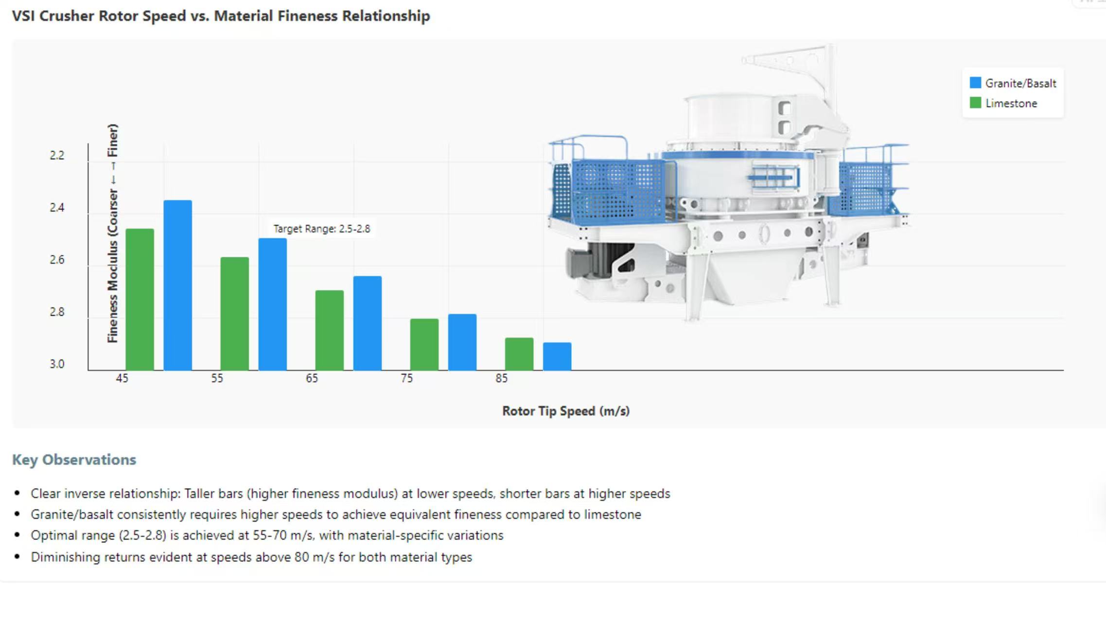
Rotor tip speed represents the most influential adjustable parameter in VSI crusher operations for fineness modulus control, directly determining impact energy transfer and consequent fragmentation intensity. Modern crushers typically operate within tip speed ranges of 45 to 85 meters per second, with higher velocities generating increased centrifugal forces that produce finer output gradation. The relationship between rotational velocity and product fineness follows predictable patterns, enabling operators to systematically manipulate output characteristics through precise speed adjustments. This direct correlation stems from fundamental physics principles governing kinetic energy transfer during particle impact events within the crushing chamber.
Velocity-Energy Relationship in Particle Fragmentation
Rotor Tip Speed vs. Fineness Modulus Correlation
Note: Inverse relationship between rotor tip speed and fineness modulus, with material-specific variations in response magnitude.
The kinetic energy imparted to feed material increases proportionally with the square of rotor tip speed, following established physical principles governing mass acceleration and impact force generation. This exponential relationship means that minor velocity increments produce substantial increases in fragmentation intensity, significantly influencing the resulting particle size distribution. Higher rotor speeds generate more intensive rock-on-rock and rock-on-liner impacts, producing increased fines generation through both primary fragmentation and secondary attrition processes. The controlled manipulation of this energy input enables producers to shift fineness modulus values by 0.2 to 0.5 units within operational speed ranges.
Crushing mechanism analysis reveals that optimal velocity settings must balance fragmentation efficiency against undesirable overgrinding effects that generate excessive micro-fines. The precise relationship between rotor speed and product gradation varies according to feed material characteristics, particularly rock hardness, fracture toughness, and natural cleavage properties. Extensive industry experience demonstrates that granite and basalt typically require higher tip speeds than limestone and dolomite to achieve equivalent fineness modulus values, reflecting their respective mechanical properties and breakage characteristics.
Operational Protocols for Rotational Speed Adjustment
Safe rotational speed adjustment requires systematic procedures beginning with comprehensive equipment inspection to verify mechanical integrity before parameter modification. Modern VSI crushers incorporate variable frequency drive systems that enable precise rotor speed control through electronic interface panels, allowing operators to implement changes during operation without mechanical intervention. The adjustment process should follow incremental methodology, with speed modifications not exceeding 5% between successive evaluation periods to prevent destabilization of the crushing chamber dynamics. Each adjustment requires sufficient operational time for system stabilization before product sampling and analysis.
Documentation protocols must accompany speed adjustments, recording previous and new operating parameters alongside corresponding product quality measurements. This systematic approach facilitates the development of plant-specific operational databases that correlate crusher settings with output characteristics under various feed material conditions. Safety considerations necessitate complete isolation of energy sources before physical inspection or maintenance activities, with particular attention to rotor locking mechanisms and drive belt tensioning systems that ensure operational reliability.
Consequences of Excessive Rotational Velocity
Rotor speeds exceeding optimal operational ranges produce several detrimental effects including accelerated wear component deterioration, increased energy consumption, and excessive micro-fines generation. Wear rates on impact elements follow exponential relationships with impact velocity, potentially reducing service life by 40-60% when operating 20% above recommended parameters. Energy consumption increases disproportionately at higher velocities due to greater air resistance and mechanical friction losses within the crushing chamber and drive systems. These factors collectively diminish operational efficiency while increasing production costs through reduced component longevity and higher power requirements.
Excessive fines generation represents another significant concern, with micro-particles below 75μm potentially exceeding allowable limits in construction sand specifications. These ultra-fine particles adversely affect concrete performance by increasing water demand and compromising strength development through interference with cement hydration processes. Modern environmental regulations increasingly restrict particulate emissions from crushing operations, necessitating additional dust collection equipment when operating at extreme rotor velocities. The economic implications include both capital investment in pollution control technology and ongoing operational expenses for system maintenance and disposal of collected fines.
Velocity Optimization Through Performance Monitoring
Optimal rotor speed determination requires continuous performance monitoring through systematic product sampling and analysis procedures. The most effective methodology involves establishing baseline performance metrics at standard operating conditions before implementing controlled speed variations while maintaining consistent feed material characteristics. Data collection should include power consumption measurements, production throughput rates, and comprehensive particle size distribution analysis to evaluate the complete impact of velocity adjustments. This empirical approach enables operators to identify crusher-specific optimal settings that maximize production efficiency while achieving target product specifications.
Advanced operations employ statistical process control techniques to maintain consistent output quality, with automated monitoring systems triggering alerts when performance parameters deviate from established optimal ranges. The integration of modern sensor technology and control systems enables real-time adjustment of rotor speed in response to feed material variations, maintaining consistent product quality despite changing input characteristics. This automated approach represents the current industry standard for high-volume production facilities requiring precise quality control with minimal operational intervention.
Feed Rate and Consistency Management
Feed rate optimization represents another critical parameter for fineness modulus control, directly influencing material retention time and impact frequency within the crushing chamber. Consistent feed flow ensures stable material bed depth that promotes optimal rock-on-rock crushing action while preventing direct metal-to-particle contact that accelerates wear component deterioration. The relationship between feed rate and product gradation follows predictable patterns, with higher throughput typically producing coarser output due to reduced residence time and impact opportunities. Modern crushing facilities employ sophisticated feeding systems with mass flow meters and variable speed controllers to maintain optimal feed rates despite fluctuations in upstream operations.
Detrimental Effects of Feed Fluctuations on Product Consistency
Impact of Feed Rate Fluctuations
1
Feed Rate VariationIntermittent feeding creates alternating starvation and overload conditions
2
Unstable Crushing DynamicsIrregular particle bed depth disrupts optimal rock-on-rock crushing action
3
Product InconsistencyFluctuating fineness modulus (±0.3 units) and particle shape characteristics
4
Operational ConsequencesIncreased wear, energy inefficiency, and potential product downgrading
Note: Causal chain illustrating how feed rate fluctuations propagate through the crushing system to affect product quality.
Inconsistent feed rates generate unstable crushing chamber conditions that produce irregular product gradation and fluctuating fineness modulus values. Intermittent feeding creates alternating conditions of material starvation and overload, preventing the establishment of consistent particle bed depth essential for efficient inter-particle comminution. These fluctuations cause the crusher to operate outside design parameters, reducing efficiency while increasing wear component stress through irregular loading patterns. The resultant product inconsistency compromises quality specifications and may necessitate reprocessing or downgrading of output material.
Feed variations particularly affect the critical rock-on-rock crushing action in VSI systems, where optimal performance requires continuous material presence between the rotor and surrounding anvils or rock shelf. Starvation periods allow accelerated rotor wear through direct impact with limited material cushioning, while overload conditions reduce effective impact velocity through excessive material absorption of kinetic energy. Both scenarios diminish crushing efficiency and produce unpredictable output gradation that fails to meet precise fineness modulus requirements for quality construction applications.
Optimized Feeding Strategy for Maximum Efficiency
The optimal feeding approach for VSI crushers involves maintaining choked conditions where material completely fills the crushing chamber without exceeding operational capacity limits. This crowded chamber concept maximizes rock-on-rock crushing action while minimizing wear component contact with feed material, significantly extending service life and reducing operating costs. Modern feeding systems employ level sensors and mass flow indicators to maintain this optimal condition automatically, adjusting feeder speed in response to crusher power draw and chamber fill level indicators. This automated approach ensures consistent operation despite variations in upstream processing rates or material characteristics.
Feeder selection and configuration significantly influence performance, with vibrating feeders generally providing superior control compared to belt feeders for difficult-to-handle materials. The feeder design must accommodate maximum anticipated production rates while maintaining precise control at lower throughput requirements, ensuring operational flexibility across varying production scenarios. Proper installation geometry ensures material enters the crusher centrally and vertically, maximizing rotor efficiency and preventing uneven wear patterns that compromise long-term performance and product consistency.
Synchronized Adjustment of Feed Rate and Rotor Speed
The coordinated adjustment of feed rate and rotor speed enables precise fineness modulus control while maintaining optimal production efficiency across varying operational requirements. This synchronized approach recognizes the interdependent relationship between these parameters, where feed rate primarily influences product coarseness while rotor speed controls fines generation intensity. The most effective methodology involves establishing a baseline relationship through systematic testing, then implementing controlled variations to develop plant-specific operational guidelines. Modern control systems can automate this coordination through programmed logic controllers that maintain optimal parameter relationships despite changing production targets.
Practical implementation typically follows sequential adjustment patterns, beginning with rotor speed establishment based on target fineness modulus requirements, then optimizing feed rate to maximize throughput while maintaining product quality. This approach ensures that energy utilization remains efficient while achieving desired output specifications. Documentation of successful parameter combinations for different material types and production targets facilitates rapid operational adjustments when changing between products or addressing variations in feed material characteristics.
Feed Material Characteristics and Preparation Requirements
Feed material properties significantly influence optimal crusher parameters, particularly moisture content, clay presence, and initial particle size distribution. High moisture levels exceeding 3-5% typically necessitate reduced feed rates to prevent material buildup and potential blockages within the crushing chamber and discharge pathways. Clay-containing materials require special consideration, as cohesive particles can accumulate on rotor components and chamber surfaces, gradually reducing effective volume and altering crushing dynamics. Proper feed preparation through prior screening and potential washing ensures consistent crusher operation and product quality.
The initial particle size distribution from upstream crushing operations directly affects VSI performance, with optimally graded feed material producing superior results compared to poorly distributed input. Modern crushing circuits typically employ primary and secondary crushing stages before VSI processing to ensure appropriate feed gradation that maximizes efficiency and product quality. The integration of pre-screening systems removes undersize material that would otherwise consume energy without meaningful size reduction, improving overall circuit efficiency while reducing wear component consumption.
Crushing Chamber Configuration and Airflow Dynamics
Crushing chamber design and internal airflow patterns significantly influence product gradation through their effect on particle retention time and fine material evacuation efficiency. Modern VSI crushers offer various chamber configurations optimized for different applications, including open-sided rotors for maximum production capacity and closed rotors for enhanced particle shape modification. The geometric relationship between rotor diameter, chamber volume, and material flow path determines the number of impacts each particle experiences before discharge, directly affecting the resulting size distribution. Airflow dynamics within the chamber further influence fine particle separation, with internal vortex patterns carrying micro-fines toward discharge outlets while retaining larger particles for additional fragmentation.
Rotor Design Configuration and Particle Retention Time
Open rotor designs typically feature larger internal volumes that reduce particle velocity and impact frequency, resulting in shorter retention times and coarser output gradation. These configurations maximize throughput capacity while minimizing energy consumption per ton of processed material, making them suitable for applications prioritizing production volume over precise gradation control. Closed rotor designs incorporate internal cascading systems that recirculate particles through the impact zone multiple times, increasing retention duration and producing finer output with improved particle shape characteristics. The selection between these configurations represents a fundamental decision influencing the crusher's capability to achieve specific fineness modulus targets.
Hybrid rotor designs have emerged recently, offering adjustable features that enable operators to modify internal flow patterns according to production requirements. These innovative systems provide operational flexibility, allowing single machines to produce different product grades without component changes. The adaptability proves particularly valuable in operations requiring frequent product changes or producing multiple sand specifications from variable feed materials. The mechanical complexity of these systems necessitates sophisticated maintenance protocols but delivers significant operational advantages through enhanced flexibility.
Airflow Manipulation for Fine Particle Control
Internal airflow patterns naturally develop within operating VSI crushers due to rotor-induced turbulence and pressure differentials between feed and discharge points. These air currents influence fine particle movement, carrying micro-fines toward discharge outlets while potentially retaining intermediate particles for additional fragmentation. Modern crusher designs incorporate adjustable airflow systems that enable operators to manipulate these internal currents, enhancing or restricting fine particle evacuation according to production requirements. This controlled airflow represents another parameter for fineness modulus adjustment, particularly influencing the proportion of particles below 150μm that significantly affect the calculated value.
Airflow adjustment typically involves modifying external ventilation ports or integrating supplemental air injection systems that alter internal pressure gradients. Increased airflow generally enhances fine particle removal, producing coarser products with higher fineness modulus values, while restricted airflow retains finer particles for additional comminution. The optimal configuration depends on specific production targets and material characteristics, requiring empirical determination through systematic testing. Proper airflow management also influences dust emission control, with well-designed systems reducing environmental impact while maintaining product quality.
Liner Wear Effects on Crushing Chamber Performance
Progressive liner wear gradually alters crushing chamber geometry, modifying material flow patterns and impact dynamics that ultimately affect product gradation. Worn liners typically increase effective chamber volume, reducing material velocity and impact energy while potentially creating irregular flow paths that compromise crushing efficiency. These geometric changes subtly influence product characteristics, often producing gradual fineness modulus drift that requires compensatory parameter adjustments. Regular liner thickness monitoring and scheduled replacement prevent significant performance deviation and maintain consistent product quality.
The economic implications of liner wear extend beyond replacement costs to include production inefficiencies and potential quality non-conformities if left unaddressed. Modern operations employ laser scanning systems to create digital models of liner profiles throughout their service life, enabling predictive replacement scheduling before performance degradation affects product specifications. This proactive approach maintains consistent operation while optimizing component utilization, representing best practice in modern aggregate production management. The data collected also informs liner material selection decisions, identifying alloys and designs that maximize service life under specific operating conditions.
Chamber Configuration for Specific Material Types
Crushing Chamber Configuration Comparison
| Configuration Type | Particle Retention Time | Typical Fineness Modulus Range | Best For Material Types |
|---|---|---|---|
| Open Rotor | Shorter (1-2 impacts) | 2.7 - 3.0 | Limestone, dolomite, low abrasion materials |
| Closed Rotor | Longer (3-5 impacts) | 2.3 - 2.6 | Granite, basalt, high strength materials |
| Hybrid Rotor | Adjustable (1-5 impacts) | 2.4 - 2.9 | Variable feed, multiple product requirements |
Note: Comparative analysis of crushing chamber designs showing performance characteristics and material suitability.
Optimal crushing chamber configuration varies according to processed material characteristics, particularly hardness, abrasiveness, and natural fracture properties. Hard, abrasive materials like granite and quartzite typically benefit from robust chamber designs with enhanced wear protection and controlled impact angles that maximize efficiency while minimizing component deterioration. Softer materials like limestone and dolomite permit more aggressive chamber geometries that prioritize production rate and particle shape modification. The selection process should consider both immediate production requirements and long-term operational costs, balancing initial investment against sustained performance and maintenance expenditures.
Modern crusher manufacturers offer application-specific chamber configurations optimized for particular material types and production targets, incorporating extensive field experience into design improvements. These specialized configurations typically deliver superior performance compared to universal designs, though they limit operational flexibility for facilities processing multiple material types. Operations handling diverse feed materials often select compromise configurations that provide acceptable performance across their production range rather than optimal performance for specific materials. This decision represents a strategic balance between operational flexibility and peak efficiency.
Closed-Circuit System Screening Efficiency
Closed-circuit crushing configurations incorporate screening equipment that separates crusher discharge into finished product and oversize material that returns for further processing. This arrangement enables precise control over final product gradation through manipulation of discharge characteristics and recirculating load properties. The screening efficiency directly influences crusher performance by determining the size distribution of returned material, which subsequently affects fragmentation dynamics within the crushing chamber. Modern high-efficiency screens achieve separation accuracy exceeding 95%, ensuring that only appropriately sized material returns for additional processing while minimizing energy waste through unnecessary recirculation.
Screen Media Selection for Optimal Classification
Screen aperture selection establishes the critical separation point determining both finished product specification and crusher feed characteristics in closed-circuit operations. The aperture size must correspond to the desired product top size while accommodating practical considerations including screen efficiency, material blinding tendencies, and wear characteristics. Modern screen systems employ multiple deck configurations that separate material into several size fractions, with the intermediate fraction typically returning to the crusher for additional processing. This multi-stage separation enhances overall circuit efficiency by ensuring that only material requiring additional reduction returns to the crusher.
Screen media selection involves balancing separation efficiency against service life and operational considerations, with polyurethane panels offering superior wear resistance while wire cloth provides better open area for high-moisture materials. The optimal choice depends on specific application requirements, including material abrasiveness, production rates, and desired product specifications. Modern screening systems incorporate tensioning mechanisms and vibration patterns that minimize blinding while maximizing separation efficiency, particularly for difficult-to-screen materials containing high proportions of near-size particles.
Recirculating Load Optimization Strategies
The recirculating load ratio represents the proportion of screen oversize returned to the crusher relative to fresh feed input, typically ranging between 100% and 200% in efficient operations. This parameter significantly influences both production rate and product gradation, with higher ratios generally producing finer output through increased processing of already-reduced material. Optimal ratio determination requires balancing product quality requirements against energy consumption and component wear considerations, with excessively high ratios diminishing overall circuit efficiency despite improving product specifications. Modern control systems continuously monitor and adjust this ratio through variable speed feeders and crusher parameter modifications.
The size distribution of recirculated material equally influences crusher performance, with well-graded feed promoting stable operation while poorly distributed material causes fluctuating conditions. Screening system efficiency directly affects this characteristic, with high-performance screens producing consistent oversize gradation that enables stable crusher operation. Operations should regularly verify screen performance through particle size analysis of both finished product and recirculating stream, identifying degradation before it affects overall circuit performance. This proactive approach maintains consistent product quality while optimizing energy utilization and component service life.
Circuit Configuration for Specific Product Requirements
Closed-Circuit System Flow & Screening Efficiency
Screening Efficiency Impact on Fineness Modulus Control
High-efficiency screens (>95% separation) maintain consistent recirculating load gradation
Optimal recirculating load ratio: 100-200% of fresh feed for balanced operation
Screen aperture selection directly establishes target product top size (typically 4.75mm for sand)
Multi-deck configurations enable simultaneous production of multiple gradations
Note: All system components aligned horizontally in a single row, with the 4th arrow adjusted to point right, showing complete material flow.
Closed-circuit arrangements offer numerous configuration possibilities that influence final product characteristics, particularly through the strategic combination of multiple crushing and screening stages. Simple single-crusher circuits provide basic control capabilities, while multi-stage arrangements enable precise manipulation of specific size fractions through selective processing. The most sophisticated circuits employ split-stream processing where material is separated into multiple size ranges that receive different treatment before recombining into final product. These advanced configurations achieve superior gradation control but require significant capital investment and operational complexity.
Circuit flexibility represents another important consideration, with adaptable systems capable of producing multiple product specifications from similar feed material through simple configuration changes. This capability proves particularly valuable in operations serving diverse markets or requiring rapid product changes according to project requirements. Modern control systems facilitate these transitions through pre-programmed parameter sets that automatically adjust multiple circuit components to achieve target specifications. The operational efficiency gained through these systems often justifies their implementation costs through reduced changeover time and improved product consistency.
Performance Monitoring and Circuit Optimization
Continuous performance monitoring enables closed-circuit optimization through systematic data collection and analysis of key operational parameters. Modern operations employ sophisticated instrumentation that measures power consumption, mass flow rates, and particle size distribution at multiple circuit points, providing comprehensive performance assessment. This data facilitates identification of inefficiencies and optimization opportunities, enabling incremental improvements that collectively enhance overall circuit performance. The most advanced systems employ machine learning algorithms that continuously refine operational parameters based on historical performance data, achieving autonomous optimization without operator intervention.
Regular circuit audits represent established best practice, involving comprehensive sampling and analysis campaigns that verify performance across the entire production system. These detailed assessments typically occur quarterly or following significant operational changes, providing benchmark data for continuous improvement initiatives. The audit process should examine individual component performance and their integration within the overall system, identifying bottlenecks and optimization opportunities that may not be apparent during normal operation. This systematic approach ensures sustained peak performance while maintaining consistent product quality across extended production periods.
Systematic Parameter Adjustment Methodology
Systematic Parameter Adjustment Protocol
Establish baseline performance under standardized conditions with comprehensive sampling
Implement single-variable adjustments (beginning with rotor speed) while maintaining other parameters constant
Conduct systematic sampling (15-30 minute intervals) and laboratory analysis of complete gradation
Document results and repeat adjustment cycle until target fineness modulus is consistently achieved
Validate optimal parameters under full production conditions and implement as standard operating procedure with continuous monitoring
Note: Structured protocol for systematic parameter adjustment to achieve and maintain target fineness modulus values.
Effective fineness modulus control requires implementation of structured adjustment protocols that ensure systematic parameter modification and comprehensive performance verification. This methodological approach begins with baseline establishment under standardized conditions, proceeds through controlled single-variable adjustments, and culminates in documented optimal parameter sets for specific production scenarios. The process emphasizes data-driven decision-making through regular sampling and laboratory analysis, avoiding subjective assessments that often produce inconsistent results. Modern operations increasingly digitalize this methodology through integrated control systems that automate data collection and analysis while providing operational guidance based on historical performance patterns.
Baseline Establishment Under Standardized Conditions
Initial baseline documentation involves operating the crushing circuit under standardized parameters while comprehensively characterizing both input and output material properties. This foundational assessment should continue for sufficient duration to establish normal performance variation ranges, typically encompassing multiple production shifts under consistent conditions. The resulting data provides reference points for subsequent adjustment phases, enabling objective evaluation of parameter change effects. Baseline documentation must include complete particle size distribution analysis rather than fineness modulus values, as the comprehensive gradation data reveals subtler effects of parameter adjustments.
The baseline phase also serves to verify proper equipment function and identify potential mechanical issues that might compromise adjustment validity. Comprehensive inspection should confirm optimal component condition, proper alignment, and appropriate operational settings before commencing systematic parameter modification. This preliminary verification prevents misinterpretation of adjustment results due to underlying mechanical deficiencies rather than parameter effects. The established baseline becomes the reference for all subsequent optimization efforts, making its accuracy and completeness fundamentally important for successful fineness modulus control implementation.
Single-Variable Adjustment Principle Implementation
The single-variable adjustment methodology represents a fundamental scientific approach that isolates parameter effects by changing only one operational factor while maintaining others constant. This systematic procedure ensures unambiguous attribution of observed performance changes to specific parameter modifications, avoiding confounding interpretations that arise when multiple variables change simultaneously. The methodology requires disciplined adherence throughout the adjustment process, with operators resisting the temptation to implement multiple changes despite production pressures. This approach ultimately produces more reliable results and establishes clearer understanding of parameter interactions within the crushing system.
Practical implementation involves establishing adjustment sequences that progress from most influential to secondary parameters, typically beginning with rotor speed modifications before addressing feed rate and subsequent variables. Each adjustment should be sufficiently conservative to avoid destabilizing the system, with performance monitoring continuing until equilibrium reestablishes before further changes. Documentation must meticulously record each parameter modification alongside corresponding performance measurements, creating a comprehensive database that supports future operational decisions. This rigorous approach may require temporary production compromises but delivers superior long-term control capabilities.
Systematic Sampling and Laboratory Analysis Protocols
Representative sampling constitutes another critical element in successful parameter optimization, requiring carefully designed procedures that ensure collected samples accurately reflect production conditions. Modern operations employ automated sampling systems that extract representative material increments at predetermined intervals, typically every 15-30 minutes during adjustment phases. These systems minimize sampling bias while ensuring consistent procedure application across extended optimization campaigns. Manual sampling remains acceptable when properly executed following established protocols that account for material segregation tendencies and process variations.
Laboratory analysis must employ standardized procedures that ensure result consistency and comparability across different time periods and personnel. The specific methodology should comply with relevant industry standards, typically involving sieve analysis using calibrated equipment following prescribed operational protocols. Results documentation should include complete particle size distribution data rather than仅仅 fineness modulus values, as the comprehensive gradation curve reveals subtler effects of parameter adjustments. Modern laboratories increasingly employ laser diffraction analysis alongside traditional sieving, providing additional particle morphology information that enhances process understanding.
Optimal Parameter Documentation and Implementation
Successful parameter optimization culminates in comprehensive documentation that captures established optimal settings for various production scenarios and material types. This documentation should include complete operational parameters alongside corresponding product characteristics, enabling operators to quickly implement proven settings when production requirements change. Modern digital systems facilitate this documentation through automated data logging and centralized storage, with intuitive interfaces that make historical optimization results readily accessible to operational personnel. This institutional knowledge preservation proves particularly valuable during personnel changes or extended production interruptions.
Implementation of optimized parameters requires systematic verification to ensure anticipated performance under full-scale production conditions. This validation phase should confirm that laboratory-scale results translate effectively to industrial operation, with particular attention to consistency across extended production periods. Successful validation enables formal adoption of the optimized parameters as standard operating procedures, with control systems configured to maintain these settings during normal operation. Continuous monitoring ensures sustained performance, with alert systems triggering when deviations occur that might require parameter recalibration or equipment maintenance.