How to Know When to Turn or Replace Blow Bars in a Mobile Impact Crusher
Blow Bar Management Workflow
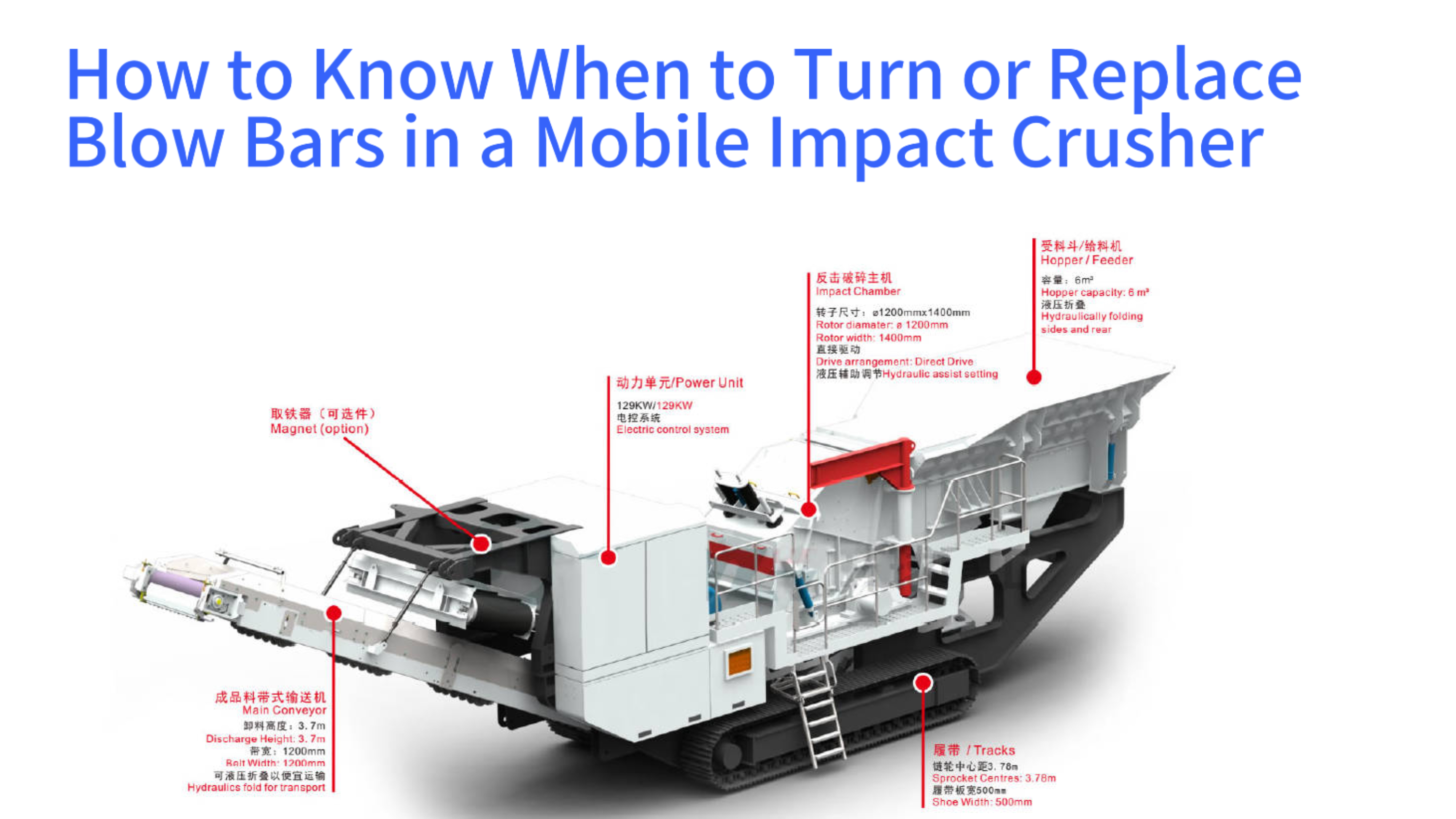
Blow bars are the core consumable components within a mobile impact crusher, directly responsible for the high-energy fragmentation of feed material. The condition of these wear parts critically influences the machine's crushing efficiency, final product shape, and overall operational cost. A systematic and data-driven approach to monitoring blow bar wear, determining the optimal point for rotation, and scheduling timely replacement is essential for maintaining productivity, ensuring operational safety, and controlling expenses. This guide details a comprehensive methodology for blow bar management, moving beyond subjective visual inspection towards a quantified evaluation process. It addresses the fundamental mechanisms of uneven wear, establishes clear inspection protocols and measurement criteria, defines the precise conditions under which bars should be rotated or replaced, and analyzes key variables affecting wear rates. The objective is to empower operators and maintenance personnel with the knowledge to extend component life, prevent catastrophic failures, and optimize the total cost of ownership for their mobile crusher assets through informed, predictive maintenance decisions.
Understanding Wear Mechanisms and the Origins of Uneven Wear
Root Causes of Asymmetric Blow Bar Wear
Accurate assessment of blow bar condition necessitates a foundational understanding of their operational environment and failure modes. Within a mobile impact crusher, the rotor assembly spins at high speed, causing the mounted blow bars to strike incoming feed material with tremendous kinetic energy. This repeated, high-intensity impact, combined with abrasive sliding and grinding actions, gradually erodes the surface material of the bars. The development of uneven wear patterns is not random but results from a combination of factors related to feed characteristics, machine configuration, and operational parameters. Common wear profiles include central indentation on the leading impact face, differential wear between the two ends of a bar, and localized gouging caused by irregular feed. Comprehending the root causes of these specific wear morphologies forms the essential basis for subsequent targeted inspection, judgment, and maintenance planning. Relying solely on instinct or generalized experience often leads to the extremes of premature replacement, which wastes capital, or excessive usage, which risks severe equipment damage.
The working principle of an impact crusher subjects the blow bars to a complex set of forces. Upon collision, the bar experiences a primary impact force normal to the material, shearing forces as fragments slide across its surface, and abrasive wear from finer particles. The central region of the leading edge typically wears fastest due to the concentration of direct impact energy. Non-uniform feed distribution, such as material predominantly entering one side of the feed opening, creates an imbalance in workload, leading to one end of the blow bar wearing more rapidly than the other. Variations in feedstock composition, including changes in hardness and abrasiveness, also contribute to irregular wear. Incorrect adjustment of the secondary and tertiary crushing aprons can cause material to ricochet within the chamber, striking the bars in unpredictable patterns and accelerating localized loss.
Impact Crushing Principles and Blow Bar Force Analysis
The crushing action in an impact crusher is fundamentally kinetic. Material is fed into the crushing chamber where it encounters the rapidly rotating blow bars. These collisions transfer energy from the rotor to the feed, causing it to fracture along its natural grain boundaries. The blow bar itself is subjected to extreme and cyclical loading during each impact event. This loading includes compressive stress at the point of contact, tensile stress on the bar's underside, and significant frictional heat generation. The leading edge bears the brunt of this mechanical punishment, explaining its propensity for rapid wear. Over time, this concentrated erosion creates a characteristic concave profile on the bar's working face, a clear indicator of its service history and remaining useful life.
Advanced analysis of the stress distribution across a blow bar during operation reveals why failure often initiates at specific points. Finite element modeling shows stress concentrations near the locking mechanisms and at the transition zones between the wear-resistant overlay and the base metal. Understanding these stress patterns helps in designing more durable bar profiles and informs inspection priorities. For instance, areas of high cyclic stress are more susceptible to fatigue cracking, which can precede catastrophic failure. Therefore, a thorough inspection must look beyond simple thickness measurement and actively search for hairline cracks in these critical zones, especially after the bar has been rotated and the previously hidden surface becomes the new impact face.
Key Factors Leading to Asymmetric Wear Patterns
Several operational and mechanical factors conspire to create asymmetric or irregular wear on blow bars. Uneven feeding stands as a primary culprit. When the material flow is not centered within the crusher's feed opening, one side of the rotor and its blow bars receives a disproportionate amount of work. This leads to accelerated and uneven wear along the length of individual bars. Fluctuations in material properties, such as processing a mix of soft limestone and highly abrasive granite, cause inconsistent wear rates that are difficult to predict and manage. The rotational speed of the rotor, defining the tip speed of the blow bars, is another critical variable. Excessively high tip speeds may improve fragmentation for certain materials but dramatically increase wear rates and the risk of imparting unfavorable elongated shapes to the product.
Mechanical condition of the crusher itself plays a significant role. Worn or misadjusted impact aprons and breaker plates fail to properly contain and redirect material within the crushing chamber. This can cause a recycling effect where partially crushed pieces are not efficiently ejected and instead recirculate, repeatedly striking the blow bars and causing unnecessary secondary wear. Similarly, worn feed chute liners can cause material to funnel incorrectly onto the rotor. Even the method of feeding, whether continuous and even or sporadic and bulky, influences wear patterns. A well-maintained crusher with a consistent, centered feed of predictable material is the ideal scenario for promoting uniform blow bar wear and maximizing component life.
Blow Bar Condition Assessment: Daily Inspection and Key Measurement Metrics
Blow Bar Inspection & Measurement Metrics
Establishing a standardized blow bar condition assessment process is pivotal for transforming subjective judgment into objective, actionable data. This requires operators and maintenance teams to move beyond casual visual glances and adopt systematic checklists and quantitative measurement tools. Daily inspections should be conducted with the machine fully shut down and locked out according to strict safety protocols. The initial visual examination focuses on the overall wear profile of each bar, looking for severe notches, deep gouges, and any signs of cracking. However, qualitative observation alone is insufficient for precise decision-making regarding rotation or replacement. It is imperative to introduce key quantifiable metrics.
The most critical measurements are the remaining thickness and remaining length of the blow bar. Using precision tools like vernier calipers, depth gauges, or custom-made templates, maintenance personnel can take regular readings at designated points on each bar. Comparing these measurements to the original dimensions of a new blow bar allows for accurate calculation of wear rates, typically expressed in millimeters of material lost per hundred operating hours. Equally important is recording the uniformity of wear by measuring thickness differences between the two ends and across the width of the bar. This collected dataset forms the empirical foundation for determining whether a blow bar has reached the permissible threshold for rotation or has been consumed to its safe minimum limit, necessitating replacement. This data-centric approach is as vital for managing a mobile impact crusher as it is for monitoring the liners in a stationary cone crusher.
Safe Shutdown and Visual Inspection Standard Procedure
Conducting a safe and effective inspection begins long before any measurements are taken. The mobile impact crusher must be brought to a complete stop, and the engine or power source must be switched off and isolated. All potential energy sources, such as hydraulic accumulators, should be safely discharged. The area around the crusher must be clear, and personal protective equipment, including hard hats, safety glasses, and gloves, must be worn. The visual inspection then proceeds in a methodical manner. Each blow bar should be examined for obvious damage. Special attention is paid to the edges of the bar, which can become thin and sharp, and to the areas immediately surrounding the locking bolts or wedges, common initiation points for stress cracks. Any accumulation of packed material around the bar or rotor should be noted and removed, as it can mask underlying wear or cracks.
A detailed visual inspection log should accompany each maintenance session. This log records observations for each individual bar using a consistent numbering system. Notes should include descriptors of the wear pattern, the presence and location of any visible cracks, the condition of the locking hardware, and any signs of material buildup. Photographs taken from consistent angles during each inspection can provide an invaluable visual history of wear progression. This disciplined approach to visual checks not only informs immediate maintenance actions but also builds a long-term record that can reveal trends related to specific material types or operational conditions, contributing to more sophisticated predictive maintenance strategies.
Key Dimension Measurement Tools and Point Selection
Transitioning from qualitative to quantitative assessment requires the correct tools and a defined measurement protocol. A high-quality digital vernier caliper is essential for measuring remaining thickness and length. For measuring wear depth in the concave center of a bar, a depth gauge or a set of feeler gauges used with a straight edge placed across the bar's wings is effective. Some operations create simple reusable templates from sheet metal that match the profile of a new blow bar; placing this template over a worn bar quickly highlights the extent of material loss. The selection of measurement points must be consistent and representative. Standard practice involves taking thickness measurements at three points along the length of the bar: one near each end and one in the center. Additionally, the thickness at both the leading edge and a point slightly back from the edge should be recorded to understand the wear profile's shape.
Establishing these fixed measurement points allows for accurate tracking over time. It is advisable to gently mark these points with a center punch or paint marker to ensure repeatability across inspection intervals. The length of the bar should also be measured, as excessive shortening can affect the clearance between the bar tips and the aprons, impacting crushing performance. All measurements should be recorded in a dedicated log or digital spreadsheet against the bar's unique identifier and the crusher's current operating hour meter reading. This historical data is the raw material for calculating wear rates, predicting remaining life, and making financially sound decisions about when to rotate or replace a set of blow bars, a principle equally applicable to managing wear parts in a hammer crusher.
Decision Criteria and Operational Standards for Blow Bar Rotation
Blow Bar Rotation Eligibility Criteria
40-50% of original thickness (industry standard)
No localized thin spots or deep gouges
Sufficient material to absorb impact loads
No visible cracks (hairline or larger)
Intact mounting surfaces/grooves
No deformation of bar geometry
Even wear profile (no extreme crescent shape)
Opposing face presents optimal crushing angle
No impact on product gradation post-rotation
Blow bar rotation, commonly referred to as "turning," is the practice of removing a worn bar and reinstalling it 180 degrees from its original orientation. This presents a fresh, less-worn surface to the incoming material, effectively doubling the potential service life of the component. This procedure is one of the most cost-effective measures for reducing wear part expenses per ton of processed material. However, not every worn blow bar is a suitable candidate for rotation. The decision hinges on a rigorous evaluation of whether the bar, after being turned, will retain sufficient structural integrity, secure mounting, and effective crushing geometry for another service cycle. An incorrect decision to rotate a compromised bar can lead to in-service fracture, loosening of mounting hardware, or even catastrophic ejection from the rotor, resulting in extensive secondary damage to the crusher's interior and prolonged, costly downtime.
Therefore, establishing clear, measurement-based criteria for permitting rotation is non-negotiable. These criteria must be strictly adhered to, and the rotation process itself must follow a meticulous, standardized protocol. The evaluation focuses on the condition of the bar's backside, which will become the new impact face. It must have enough remaining base material to withstand the impending impacts without flexing or cracking. The wear on the original impact face must not have progressed so far that it has undermined the bar's core structure or damaged its mounting features. The presence of any cracks, regardless of size, typically disqualifies a bar from rotation, as these flaws will likely propagate rapidly under the stress of its new role. A disciplined approach to rotation maximizes economic benefit while squarely prioritizing equipment and personnel safety.
Suitable Wear Condition Profile for Rotation
A blow bar is generally considered suitable for rotation when it meets specific, quantifiable conditions related to its remaining material. A common industry guideline is that the minimum remaining thickness at any point on the bar should be no less than 40% to 50% of its original thickness. This ensures a substantial safety margin of material to absorb impact energy. The wear profile should be relatively even, without deep, localized notches or gouges that act as stress concentrators. Crucially, the bar must be free of any visible cracks, including fine hairline fractures, especially around bolt holes and the edges. The mounting surfaces and locking grooves must be intact and free of deformation, ensuring the bar can be resecured with the proper torque and clamping force.
Beyond these measurable thresholds, the overall geometry of the bar must still be functional. If the original impact face is worn into an extreme crescent shape, the opposing face may not present an optimal angle for efficient crushing upon rotation. This can lead to reduced productivity and altered product gradation. The decision to rotate should therefore integrate both hard metrics—minimum thickness, absence of cracks—and softer engineering judgments about the bar's ability to perform effectively in its new orientation. Maintaining detailed records of which bars were rotated and their subsequent performance provides valuable feedback to refine these rotation criteria over time, tailoring them to the specific conditions of a particular aggregate processing operation.
Safe and Standardized Rotation Procedure Steps
The physical process of rotating blow bars must be executed with precision to ensure a safe outcome and reliable operation. The procedure begins with the safe isolation and lockout of the crusher. The access doors to the rotor are opened, and any residual material is cleared. Using the correct tools, the locking wedges, bolts, or retainers for the target blow bar are carefully loosened and removed. The bar is then lifted out, cleaned of all debris, and placed on a stable work surface for a thorough inspection, focusing on the criteria for rotation. If the bar passes inspection, it is rotated 180 degrees along its longitudinal axis. The mounting area on the rotor must also be cleaned meticulously.
The bar is then repositioned in its new orientation. It is critical to install new locking hardware as specified by the manufacturer; reusing old, stressed bolts or wedges is a common source of failure. The fasteners must be tightened in the correct sequence and to the precise torque value using a calibrated torque wrench. Uneven or insufficient torque can allow the bar to work loose during operation. Once all bars scheduled for rotation are reinstalled, a final visual check confirms they are seated correctly and all fasteners are secure. Only after this comprehensive procedure is complete should the crusher be considered ready for return to service. This level of procedural rigor is essential for maintaining the reliability of a mobile impact crusher working in demanding environments.
Precise Determination of Final Replacement Timing and Risk Warning
Blow Bar Replacement Criteria
Rotation extends a blow bar's service life by one cycle, but eventually, both working faces become consumed, mandating replacement. Determining the optimal replacement timing requires navigating the balance between the risk of catastrophic failure from overuse and the inefficiency of premature change-outs. This decision should be driven by a combination of safety mandates and economic analysis, not merely by whether the bar appears to still be functioning. The primary technical criterion is the minimum allowable remaining thickness. When wear reduces a blow bar's thickness below the manufacturer's specified safety limit—often between 20% and 30% of the original dimension—the remaining material may lack the structural strength to withstand impact loads, making sudden fracture highly probable.
Even if the safety thickness limit has not been reached, economic factors may dictate replacement. Severe wear alters the bar's aerodynamic profile within the crushing chamber, diminishing its kinetic energy transfer efficiency. This inefficiency manifests as a noticeable drop in production throughput, a coarser product size, and a significant increase in specific energy consumption. When the cost of lost production and extra fuel or electricity surpasses the cost of a new set of blow bars, replacement becomes the economically rational choice. Developing a predictive replacement schedule based on historical wear rate data and planned production targets is the most effective strategy for avoiding unplanned downtime, optimizing maintenance windows, and ensuring a consistent supply of critical wear parts like blow bars.
Safety-Based Replacement Hard Standards
The absolute, non-negotiable standard for blow bar replacement is grounded in material integrity and operator safety. Manufacturers provide explicit guidelines regarding the minimum safe remaining thickness for their specific blow bar designs and materials. These values are derived from engineering calculations and material fatigue testing, accounting for the dynamic loads experienced during operation. Ignoring these specifications exposes the equipment to extreme risk. A bar worn thin is prone to bending or cracking. A complete fracture can result in large, high-velocity fragments being thrown inside the crusher chamber, causing extensive damage to aprons, liners, and the rotor itself. In a worst-case scenario, a fragment could breach the crusher housing, creating a severe projectile hazard.
Adherence to these hard limits is a fundamental responsibility of crusher management. The measurement data collected during regular inspections must be compared directly against these manufacturer-provided minimums. Any bar found at or below the specified threshold must be flagged for immediate replacement, regardless of its apparent condition or the inconvenience of an unscheduled stoppage. This proactive replacement based on quantifiable data is far less costly than reacting to a catastrophic failure, which entails not only new parts but also potentially extensive repairs to other crusher components and significant lost production. This safety-first principle is universal across crushing technology, applying equally to the mantles and concaves in a spring cone crusher.
Economic-Based Replacement Soft Standards and Predictive Planning
Beyond the hard safety line, a more nuanced economic analysis can determine an optimal replacement point that maximizes cost-efficiency. This involves monitoring key performance indicators that degrade with blow bar wear. A steady increase in the crusher's power draw, measured as amperage on the main motor, indicates the machine is working harder to achieve the same output—a sign of reduced crushing efficiency. A measurable decline in tons-per-hour throughput for the same feed material and crusher settings is another clear signal. When these performance losses reach a predefined threshold, for instance, a 15% increase in energy cost per ton or a 10% drop in production rate, the economic argument for replacement becomes compelling.
Predictive planning leverages historical wear rate data to forecast future replacement needs. By tracking how many millimeters of thickness are lost per 100 operating hours with a specific material, operators can project when a currently installed set of bars will reach the minimum thickness. This allows for the scheduling of replacement during a planned maintenance shutdown, the timely ordering of spare parts to avoid expedited shipping fees, and better budgeting for wear part expenses. This data-driven, planned approach contrasts sharply with a reactive strategy, transforming blow bar management from a source of unpredictable cost and downtime into a controlled, optimized component of operational planning, much like scheduling liner changes in a VSI crusher for consistent sand production.
Analysis of Key Variables Affecting Wear Rate and Optimization Strategies
Wear Rate Factors & Optimization Strategies
AI 0.4 (Limestone): ~500 operating hours
AI 0.8 (Granite): ~250 operating hours
Reduce rotor tip speed for abrasive materials
Wider apron gaps to minimize recirculation
Steady, centered feeding to avoid uneven wear
Regular apron/liner inspection & replacement
Clean feed chutes to prevent uneven material flow
Calibrate torque on blow bar fasteners
Maximizing blow bar service life involves proactive management of the variables that influence wear rate, moving beyond passive monitoring and replacement. Wear speed is governed by a combination of controllable and uncontrollable factors. A systematic analysis and optimization of these variables can substantially extend component life, delivering direct reductions in operational cost. The dominant factors include the characteristics of the feed material, the selected operational parameters of the crusher, and the mechanical condition of associated components. For example, processing highly abrasive material like quartzite will consume blow bars many times faster than processing softer limestone. Actively managing feed blend, adjusting machine settings for the specific material, and maintaining the entire crushing chamber in good working order are all strategies that directly combat excessive wear.
Implementing an optimization strategy requires a holistic view of the crushing process. It begins with material characterization—understanding the hardness, abrasiveness, and size distribution of the feed. This knowledge informs the selection of appropriate blow bar metallurgy and the adjustment of crusher parameters like rotor speed and apron gaps. Ensuring consistent and centered feeding prevents the uneven workload that leads to asymmetric wear. Regular maintenance of impact aprons, liner plates, and feed chutes ensures the material flow is directed optimally, preventing unnecessary recirculation and secondary wear on the bars. By controlling these variables, operators can shift from merely reacting to wear to actively managing and minimizing it, a philosophy that enhances the longevity of all jaw crusher wear parts as well.
Material Characteristics and Their Quantitative Impact
The single most significant factor determining blow bar wear rate is the abrasiveness of the processed material. This property is often quantified by the Abrasion Index, a standardized test that measures the wear caused by a sample on a standardized steel paddle. Materials with a high AI, such as granite, basalt, or gravel with high quartz content, are extremely aggressive on wear parts. In contrast, materials like limestone or recycled concrete typically have a lower AI. The correlation is direct; a material with an AI of 0.4 may allow a blow bar life of 500 hours, while a material with an AI of 0.8 might reduce that life to 250 hours under similar conditions. Understanding the AI of primary feedstocks allows for accurate forecasting of wear part consumption and cost-per-ton calculations.
Other material properties also play a role. Feed size distribution is critical. A constant feed of well-graded material that includes sufficient fines to cushion the crushing chamber promotes more efficient breakage and can reduce wear compared to processing only large, monolithic slabs. The moisture and clay content of the material can lead to packing and adhesion issues, which may indirectly accelerate wear by causing uneven loading or requiring more frequent cleaning stops that involve mechanical intervention. By characterizing the material stream and, where possible, blending or pre-screening to optimize feed gradation and consistency, operations can exert significant influence over the wear rate of their most expensive consumables.
Optimization of Equipment Operational Parameters
Crusher settings offer a direct lever for influencing wear rates and product quality. The rotor tip speed, determined by rotor diameter and rotational speed, is paramount. Higher tip speeds generate greater impact energy, which is beneficial for producing a well-shaped product in certain applications but comes at the cost of exponentially increased wear. For highly abrasive materials, reducing the rotor speed within the acceptable range for product specifications can dramatically extend blow bar life. The setting of the secondary and tertiary aprons controls the size of the crushing chamber and the number of times material is struck before exiting. A wider setting reduces recirculation and can lower wear, albeit potentially at the expense of a coarser product.
The consistency and method of feeding are operational parameters under direct operator control. A steady, metered feed that fully utilizes the crusher's width promotes even wear across all blow bars. In contrast, sporadic, bulky feeding causes shock loading and leads to localized, severe wear patterns. Utilizing a properly sized feeder and ensuring the feed chute distributes material evenly across the rotor are simple yet highly effective optimization strategies. Furthermore, operating the crusher at a consistent, optimal load rather than cycling between empty and overloaded states promotes stable conditions that are gentler on wear parts. These operational disciplines are key to cost-effective crushing in applications ranging from C D waste recycling to virgin rock processing.