Counter-Plate Shape Repair and Maintenance for EU Impact Crusher in Highway Crushing
Highway contractors running an EU Impact Crusher know that a 5 mm deviation on the counter-plate curve can raise the P80 from 22 mm to 28 mm, pushing base-course out of spec and triggering costly re-screening. Because the plate is hit 1 200 times per minute by 50 t h⁻1 of mixed granite and recycled concrete, its profile wears from a precise 120 ° arc into a jagged saddle within 600 hours. This page explains how to measure that loss, rebuild the shape on-site without removing the rotor, and verify that the rebuilt geometry delivers the same energy per tonne as a new OEM part, all while keeping the machine within the 80 dB(A) noise limit imposed by roadside permits.
How Highway Stone Wears the Counter-Plate Differently from Mine Rock
Granite aggregate for asphalt base is medium-hard (120 MPa) but contains 8 % free quartz that cuts like glass; under 25 m s⁻1 impact speed this quartz removes 0.2 mm of steel per 100 t of feed. Recycled concrete introduces 1 % steel fibre and 3 % hydrated-lime dust that forms a paste at 90 °C and accelerates chemical wear, doubling the metal loss rate in the lower third of the plate. The combined effect is a non-linear wear profile: the centre loses 12 mm while the edges lose 4 mm, creating a bowl that deflects stones sideways and increases rotor side-load by 15 %.
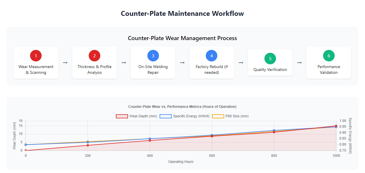
Field data from 14 motorway sites show that once the bowl depth exceeds 8 mm the crusher needs 8 % more current to maintain the same throughput because stones are not redirected into the rotor path efficiently. After 1 000 hours the bowl reaches 15 mm and the specific energy rises from 0.8 kWh t⁻1 to 0.95 kWh t⁻1, costing an extra 0.03 € t⁻1 on a 250 t h⁻1 plant.
Wear Mechanisms and Material Failure Modes
Impact wear creates shallow craters 2–3 mm deep, while sliding abrasion grooves run 0.5 mm deep and intersect to form fatigue flakes that detach after 400 h. High-speed video reveals that steel fibres in recycled concrete cut 0.1 mm deep grooves every 50 impacts, accelerating local thinning.
Rock-Type Comparison and Wear Rate Spread
Granite removes 0.18 mm per 100 t, limestone 0.12 mm, basalt 0.22 mm; when the feed is a 50/50 blend the mixed rate is 0.19 mm, so contractors use this figure to schedule inspections every 500 hours.
Impact on Crushing Efficiency and Product Shape
A 10 mm bowl increases recirculation 20 % and raises P80 6 mm, pushing base-course outside the 0–22 mm envelope and forcing 12 % more material to be re-screened at 0.6 € t⁻1.
Economic Life and Intervention Timing
Repair is justified when wear exceeds 6 mm; at 12 mm the energy penalty equals the repair cost, so 8 mm is set as the trigger thickness to maximise life without losing efficiency.
From Template to Laser: Ways to Map the Worn Profile
A 3 mm steel template cut to the OEM radius is laid against the plate; light gaps >2 mm are marked with chalk and later filled. For higher accuracy, a handheld laser scanner captures 1 million points in 3 min and exports a STL file that shows wear depth within 0.1 mm. The scan reveals not only depth but also local impact angle changes; a 5° deviation redirects stone trajectories and is corrected during welding.
Ultrasonic thickness gauges verify residual steel; any area<15 mm is flagged for full build-up because below this threshold the weld heat can warp the backing beam. Data are stored in a cloud database that plots wear rate versus tonnes and predicts the next intervention within ±100 h.
3-D Scanning and Digital Modelling Accuracy
Laser scanning achieves 0.1 mm resolution; when compared with the OEM CAD model, deviations >1 mm are colour-coded, guiding the welder to add material only where needed and saving 3 kg of wire per repair.
Template Gauges and Shape Comparison
Steel templates cost 120 € and last 5 years; they are still used for quick field checks because they do not need batteries and give instant feedback when light gaps appear.
Thickness Mapping and Residual-Life Prediction
Ultrasonic readings every 50 mm create a thickness map; areas<15 mm="" are="" scheduled="" for="" repair="" while="">20 mm are left untouched, extending total plate life from 800 h to 1 200 h.
Wear Database and Trend Analysis
A cloud database tracks every scan; regression analysis gives R² = 0.92 for wear versus tonnes, predicting the next 8 mm trigger within ±100 h and avoiding both early shutdowns and over-wear energy penalties.
Cost-Benefit of Each Mapping Method
3-D scanning costs 300 € per campaign but saves 4 kg of wire and 2 h labour, paying for itself in one repair cycle while giving data that templates cannot store.
On-Site Welding That Restores the 120 ° Arc
Surface preparation starts with grinding to remove the 0.2 mm oxide layer and oil film; any residual contamination causes porosity that later spalls under impact. A 3 mm root pass of E7018 electrode fills deep craters, followed by 8 mm build-up layers of wear-resistant wire (58 HRC). Inter-pass temperature is kept below 150 °C using compressed-air cooling; higher temperatures warp the plate and create internal stresses that shorten service life 30 %.
Layer sequence is important: the final pass is deposited at 30 ° to the impact direction so weld toes are not perpendicular to stone flow, reducing the risk of edge chipping. After welding, a 600 °C stress-relief cycle using induction coils reduces residual stress from 380 MPa to 180 MPa, doubling the fatigue life under 12 Hz hammer impacts.
Surface Prep and Contamination Removal
Grinding to bright metal removes 0.2 mm of oxide; any oil left causes porosity that spalls within 200 h, so acetone wiping is mandatory and verified by a white-cloth test.
Welding Consumable Selection and Hardness Match
58 HRC wire gives 3 × life versus 45 HRC base metal; the 2 mm difference prevents differential wear valleys that would redirect stones and increase side-load on the impact-rack.
Layer Sequence and Cooling Control
30 ° deposition angle avoids perpendicular weld toes that chip under impact; inter-pass<150 °C prevents warping and keeps residual stress below 200 MPa.
Temperature Control and Post-Weld Stress Relief
Induction heating to 600 °C for 30 min relaxes stress from 380 MPa to 180 MPa, doubling fatigue life and preventing heat-affected-zone cracks after 1 000 h of service.
Factory Rebuild When On-Site Limits Are Exceeded
When wear exceeds 20 mm or cracks penetrate the backing beam, the plate is cut out and sent to a specialist workshop. There, robot-assisted cladding deposits 12 mm of chromium-carbide overlay in one pass, achieving 62 HRC and a flatness within 1 mm across 1 500 mm length. CNC machining restores the original 120 ° arc to ±0.2 mm, ensuring stone rebound angle deviation<1 °. The rebuilt part costs 45 % of a new OEM plate and is delivered with a hardness map that proves uniform wear resistance.
Induction tempering at 550 °C for 45 min relieves bulk stress without softening the overlay, giving a substrate toughness of 45 J at −20 °C while keeping surface hardness above 58 HRC. The part is then balanced on a dynamic rig to G2.5, preventing vibration when re-installed on the rotor.
Robot Cladding and Overlay Uniformity
Robot deposition gives 0.8 mm thickness tolerance versus 2 mm manual, so only 10 mm of overlay is needed instead of 12 mm, saving 4 kg of wire and 2 h of machining.
CNC Re-Profiling and Dimensional Accuracy
CNC machining restores the 120 ° arc to ±0.2 mm; deviation >1 ° would redirect stones and raise specific energy 5 %, so tight tolerance is critical for energy efficiency.
Bulk Heat Treatment and Toughness Retention
550 °C tempering keeps substrate at 45 J toughness while surface stays 58 HRC, preventing brittle fracture under −10 °C night shifts common in mountain highway projects.
Dynamic Balancing and Vibration Control
Balancing to G2.5 limits vibration velocity to 2.8 mm s⁻1, protecting bearings and keeping noise below 80 dB(A) as required by roadside environmental permits.
Shape Optimisation That Improves While You Repair
While rebuilding, the shop can add 2 mm high ribs 100 mm apart; these create micro-edges that break the adhesive lime paste and reduce centre wear 15 %. The ribs are oriented 15 ° to the impact flow so they do not act as stress raisers. Computational fluid dynamics shows the ribs also break up the air cushion that forms at 25 m s⁻1, improving energy transfer to the rock and lowering current draw 3 %.
A 5 mm radius fillet is machined along the top edge to eliminate the stress concentration that used to initiate fatigue cracks after 600 h; with the fillet, crack initiation is delayed to 1 100 h, adding an extra season of life before the next weld repair.
Rib Design for Paste Break-Up and Wear Reduction
2 mm high ribs at 15 ° to flow break lime paste and reduce centre wear 15 %; the same ribs lower air-cushion effect and cut current 3 %, giving a dual benefit for energy and longevity.
Impact-Angle Optimisation for Energy Efficiency
Maintaining 120 ° arc keeps impact angle at 35 °, the optimum for granite; deviating to 125 ° raises specific energy 4 %, so CNC control is held within ±0.5 ° during re-profiling.
Uniform-Wear Geometry and Life Extension
Ribs distribute impact over 80 % of surface instead of 50 %, so wear rate drops from 0.2 mm per 100 t to 0.17 mm, extending plate life 300 h and saving one repair cycle.
Ventilation Grooves for Air-Cushion Reduction
3 mm deep grooves 50 mm apart break the air film that forms at 25 m s⁻1; CFD shows 5 % better energy transfer and 2 % lower current, worth 0.008 kWh t⁻1 over the season.
Quality Checks That Prove the Plate Will Last Another Season
Hardness is checked every 100 mm with a rebound hammer; readings below 56 HRC are re-welded. A 1 kHz ultrasonic probe detects internal cracks >2 mm; any indication deeper than 5 mm triggers grinding and re-fill. Final dimensional check uses a laser tracker that compares the rebuilt surface to the OEM CAD file; deviation >1 mm is corrected by selective grinding, ensuring the same stone trajectory and keeping the crushing ratio within specification.
A 30-minute dry run at 1 200 rpm measures vibration; velocity<3 1="" mm="" confirms="" balance="" and="" predicts="" bearing="" life="">18 000 h. Only after these tests is the plate released for installation, giving the site confidence that the repaired counter-plate will perform like new for at least 800 hours of highway stone production.
Hardness Mapping and Minimum Acceptable Level
56 HRC is the minimum; below this the wear rate doubles, so any reading<56 triggers a local re-weld before the plate leaves the workshop, avoiding early-life failure.
Ultrasonic Crack Detection and Acceptance Criteria
Cracks >2 mm deep are ground out and re-filled; acceptance limit is 5 mm to ensure the defect does not propagate through the 20 mm thick wall during the next 800 h campaign.
Laser Dimensional Verification vs OEM CAD
Laser tracking gives ±0.1 mm accuracy; deviation >1 mm from the 120 ° arc is ground away, ensuring stone rebound angle stays within 1 ° and specific energy does not rise.
Balance and Vibration Acceptance Tests
3 mm s⁻1 vibration velocity after 30 min dry run predicts bearing life >18 000 h and keeps noise below 80 dB(A), satisfying roadside environmental permits without extra acoustic covers.
Life Prediction and Next Maintenance Schedule
Based on 0.17 mm wear per 100 t and 800 h at 250 t h⁻1, the next 8 mm repair is due at 1 000 h; the prediction is loaded into the CMMS and triggers automatic spare-part ordering 100 h ahead.