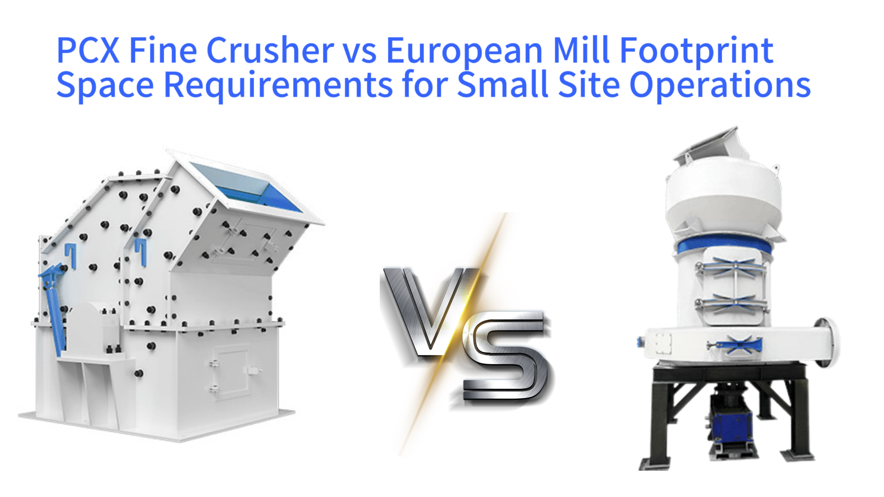
PCX Fine Crusher vs European Mill Footprint Space Requirements for Small Site Operations
Small Site Equipment Layout Planning Process
The strategic planning of industrial equipment within spatially constrained environments presents a critical challenge for small-scale aggregate producers and mineral processors. The selection between a PCX fine crusher and a European-type grinding mill extends beyond mere technical specifications, fundamentally impacting the physical layout and operational efficiency of the entire site. This analysis provides a comprehensive comparison of the spatial footprint associated with these two prevalent secondary crushing technologies. It examines the total area envelope required by each system, encompassing the host machine, its essential auxiliary components, necessary maintenance corridors, and the foundational infrastructure. The objective is to deliver a clear, actionable framework that empowers site managers and project planners to make informed capital investment decisions, optimizing limited land resources to achieve maximum production output and return on investment while ensuring safe and sustainable operations.
Redefining Footprint for Compact Industrial Sites
Industrial Equipment Footprint Components
Main machine base
Integrated components
Direct operational zone
Dust collection units
Feed/discharge conveyors
Power & control systems
Maintenance corridors
Safety perimeters
Material handling paths
Foundation footprint
Access roads/pads
Stockpile zones
The concept of a machine's footprint in an industrial setting must be understood as a multidimensional spatial requirement rather than a simple two-dimensional floor plan. For a small-scale crushing operation, the effective footprint includes the base area of the primary unit, the operational space needed for integrated or ancillary systems such as feeders and conveyors, dust collection units, and material storage bunkers. It also encompasses mandated safety perimeters, required access aisles for routine inspection and maintenance personnel, and logistical pathways for raw material intake and finished product dispatch. A holistic view must also account for vertical clearances for overhead cranes or gantries and the spatial demands of electrical switchgear and control rooms.
Small sites, typical of regional quarries, urban construction and demolition waste recycling yards, or localized aggregate plants, often face unique spatial constraints. These limitations include irregularly shaped plots, restrictive access roads that limit delivery and removal logistics, challenging topography with significant slopes, and stringent regulatory buffers from residential or environmental zones. Inadequate planning for the total equipment footprint can trigger a cascade of operational inefficiencies. These inefficiencies manifest as material handling bottlenecks, increased risks of vehicle and pedestrian conflicts, extended equipment downtime during repair due to poor accessibility, and ultimately, a hard ceiling on potential production capacity expansion due to a lack of strategic space reservation.
The Metric of Spatial Productivity Density
A valuable quantitative metric for comparing equipment in space-limited scenarios is spatial productivity density, expressed as tons of output per hour per square meter of occupied ground area. This calculation requires measuring the entire production system's occupied area, from raw material intake to final product stockpiling, against its demonstrated crushing capacity. A higher spatial productivity density indicates a more efficient use of the available land. This metric shifts the evaluation focus from the isolated size of a single machine to the performance of the integrated processing line within its spatial envelope, providing a direct link between physical footprint and economic return.
Strategic Utilization of Horizontal and Vertical Space
Industrial equipment layouts generally follow one of two spatial paradigms: horizontal expansion or vertical integration. The PCX fine crusher typically represents a horizontally oriented system, where process stages are arranged in a sequential, ground-level layout connected by belt conveyors. This approach demands a larger contiguous flat area but often simplifies maintenance access and expansion. Conversely, the European-type grinding mill employs a vertically integrated design, stacking functions like feeding, grinding, and internal classification within a tall, tower-like structure. This configuration conserves valuable ground space but imposes specific requirements on building height and demands specialized equipment for overhead maintenance, representing a distinct trade-off in spatial strategy.
The Aggregation of Auxiliary System Space
The total footprint of any crushing system is significantly influenced by its peripheral support systems. Key among these are dust suppression and collection systems, which may include large baghouse filters, cyclone separators, and associated ducting. The degree to which these components are integrated into the main machine housing versus installed as separate, free-standing units greatly affects the overall layout area. Similarly, material transfer points, surge bins, and enclosed conveyor galleries each claim additional space. A system designed with high auxiliary integration will typically present a more compact overall footprint, though potentially at the cost of increased complexity for individual component service or replacement.
Installation Foundations and Service Access Requirements
The spatial planning must extend below and around the equipment to accommodate installation and long-term service needs. Heavy machinery like crushers and mills require substantial reinforced concrete foundations, the excavation and formwork for which define a fixed ground area. Furthermore, sufficient clear space must be reserved around the equipment for the use of mobile cranes during initial installation and for major component exchanges, such as replacing a rotor or mill shaft. The width of walkways for daily operator checks and the space needed to safely remove and handle large wear parts like liners or hammers are non-negotiable parts of the operational footprint that are frequently underestimated in initial planning stages.
Spatial Anatomy of the PCX Fine Crusher System
PCX Fine Crusher System Spatial Layout
The PCX fine crusher operates on a high-impact crushing principle, utilizing a high-speed rotor equipped with wear-resistant hammers to shatter material against adjustable impact plates within an enclosed crushing chamber. The machine itself is engineered as a robust, rectangular box, housing the drive motor, rotor assembly, and hydraulic or mechanical adjustment mechanisms in a relatively consolidated form. Its design prioritizes a low profile and a compact frontal area, allowing it to fit into linear production flows commonly found in aggregate plants. However, its standalone footprint is only the starting point for spatial assessment, as its operation necessitates several critical auxiliary components.
To function within a production circuit, the PCX crusher must be seamlessly integrated with upstream and downstream equipment. A regulated feed is essential, typically provided by an apron or vibrating feeder, which requires its own footprint and a hopper for material surge capacity. The crushed product exits via a discharge conveyor, which may need space to pivot or connect to multiple downstream paths for product grading. A dust extraction system is mandatory, comprising capture hoods at the feed and discharge points connected via ducting to a remote baghouse filter, a large unit that itself can occupy an area equivalent to the crusher. The need for a return conveyor for recirculating oversized material further adds to the horizontal space claim, creating a layout that often extends in one primary direction.
Compact Host Design and Linear Process Flow
The PCX crusher achieves a degree of spatial efficiency through its integrated mechanical design, combining the power transmission, crushing chamber, and hydraulic controls within a single welded frame. This consolidated host structure minimizes its base occupancy. The process logic of the system, however, is inherently linear. Material must travel sequentially from the feed point, through the crusher, onto the discharge conveyor, and often to a screening unit before either being stockpiled or recirculated. This linearity dictates a layout that expands along the material flow path, making the system well-suited for long, narrow plots where space is available in one dimension but restricted in another.
Configuring the Dust Control System Layout
Effective dust control is a non-negotiable aspect of modern crushing operations, heavily influencing the overall site footprint. For a PCX system, dust generation is concentrated at material transfer points. While the ducting can be routed overhead to save ground space, the dust collector unit, often a pulse-jet baghouse, is a voluminous piece of equipment. Placing it adjacent to the crusher minimizes duct runs but consumes valuable ground area. Alternatively, locating it at a distance or on an elevated platform frees up primary operating space but increases initial ducting costs and fan power requirements for air movement. This spatial-economic trade-off requires careful consideration during the plant design phase.
Foundation Demands and Vibration Mitigation
The dynamic forces generated by the high-speed rotating rotor and impacting rock necessitate a substantial, isolated foundation for the PCX crusher. This foundation must be designed to absorb and dampen vibrations, preventing their transmission to surrounding structures and equipment. It typically involves a mass concrete block of significant volume, often set on vibration-damping pads or springs. The spatial requirement extends beyond the crusher's own base to include the excavation zone and any necessary access for the construction of this sub-structure. The combined weight of the machine and its foundation also imposes specific geotechnical requirements on the bearing capacity of the underlying soil, which may necessitate ground improvement in some locations.
Adaptability to Non-Ideal Topography
A potential advantage of the PCX system's linear, conveyor-based layout is its relative adaptability to sites with sloping or uneven terrain. Conveyor inclinations can be adjusted within certain limits to follow the natural ground profile, potentially reducing extensive and expensive earthworks. The individual modules—feeder, crusher, screen—can be set on graded pads at different elevations, connected by inclined conveyors. This modularity allows the layout to conform to the existing topography more readily than a system requiring a single, massive, level concrete pad. However, this approach requires precise engineering to maintain efficient material flow angles and consistent feed to the crusher.
Spatial Anatomy of the European-Type Grinding Mill System
European-Type Grinding Mill System Structure
Overall height: 15-20 meters
Grinding chamber height: 8-12 meters
Classifier section: 3-5 meters
Building clearance: 2-3 meters
Mill base: 10m×10m (100m²)
Cyclone collector: 5m×5m (25m²)
Baghouse filter: 6m×4m (24m²)
Feed elevator: 2m×3m (6m²)
Total: ~20m×20m (400m²)
The European-type grinding mill employs a fundamentally different comminution mechanism based on compressive roller grinding. Material is fed into the top of a tall, vertical mill body where it is ground between large rotating rollers and a stationary grinding ring. An integral or attached dynamic classifier at the top of the mill separates fine product, which is carried away by an air stream, from coarse material, which falls back for further grinding. This vertical integration of grinding, classification, and initial material transport within a single towering structure defines its unique spatial character. The host machine presents a small ground-level footprint but commands a significant vertical airspace.
The operation of the European mill relies on a complementary suite of external systems that complete the process circuit. A bucket elevator or vertical screw conveyor is required to lift feed material to the mill's top inlet, adding both height and a separate machine footprint. The product and transport air exit the mill to a collection system, invariably comprising a cyclone separator to drop out the bulk of the ground product followed by a baghouse filter to capture the finest particles before air is exhausted. This network of large-diameter air ducts connecting the mill, cyclone, filter, and system fan creates a complex three-dimensional piping matrix that must be carefully routed, often requiring dedicated support structures and clear overhead access lanes.
Vertical Integration and Ground Space Conservation
The primary spatial benefit of the European mill is its conservation of valuable ground area. By stacking multiple process stages vertically, it occupies a compact plot of land at grade level. This makes it a compelling choice for urban or congested industrial sites where horizontal space is at a premium but height restrictions are minimal. The entire grinding and classification process is contained within the mill housing, eliminating the need for several separate conveyors and transfer towers that would spread across the site in a horizontal circuit. This compactness can lead to a smaller overall site envelope, reducing costs associated with land acquisition, fencing, and site development for aggregate processing.
The Spatial Complexity of Air and Material Handling Networks
While the mill body itself is space-efficient, its auxiliary systems introduce significant spatial complexity. The air circuit—essential for material transport, classification, and dedusting—requires large-diameter piping that must navigate from the top of the mill to ground-level collectors and fans. These pipes often require substantial support frameworks and must maintain specific slopes and bend radii to prevent material settling and ensure smooth airflow. Their routing must avoid interference with other plant equipment, access ways, and building structures, often necessitating elevated pipe racks or dedicated galleries that consume both air rights and create shaded spaces below that may complicate other layout activities.
Dependency on Enclosed Structures and Building Services
Due to its height and the need to protect its precision mechanical and classification components from the elements, the European mill is typically housed within a building or a substantial weather enclosure. This requirement transforms the project from an open-air equipment layout to a structural building design exercise. The building must provide adequate internal clear height to accommodate the mill and its overhead crane for maintenance, along with space for the elevated feed system and ductwork. While this building consolidates operations and can improve environmental control, it represents a major capital cost and a fixed spatial commitment. The building's design must also integrate dust extraction points, electrical distribution, and HVAC for operational areas.
Foundation Requirements for a Tall, Dynamic Structure
The foundation for a European mill must be designed to support not only its substantial weight but also to ensure exceptional rigidity and stability for its tall, slender structure. Any settlement or tilt can cause misalignment of the grinding rollers, leading to accelerated wear and reduced efficiency. The foundation is typically a single, large, reinforced concrete block that extends well below frost depth and is designed to resist dynamic loads from the grinding process. Its design is critical to the long-term performance of the mill and requires thorough geotechnical investigation. The space required for this foundation, while concentrated, is significant in volume and must be positioned with precise alignment to the overall plant layout.
Head-to-Head Spatial Efficiency Analysis for Typical Small Sites
PCX Crusher vs European Mill: Spatial Comparison (50t/h Limestone Processing)
| Parameter | PCX Fine Crusher | European-Type Mill |
|---|---|---|
| Total Ground Area | ~375 m² (25m×15m) | ~400 m² (20m×20m) |
| Vertical Height Requirement | 3-5 meters | 15-20 meters |
| Spatial Productivity Density | 0.133 t/h/m² | 0.125 t/h/m² |
| Building Requirement | None (open layout) | Required (enclosed structure) |
| Expansion Flexibility | High (modular) | Limited (fixed) |
| Topography Adaptability | High | Low |
To concretely compare the two systems, consider a typical small-scale application: processing 50 tons per hour of limestone to a product size of 3mm. A PCX-based circuit would involve a feed hopper and feeder, the crusher, a discharge conveyor leading to a vibrating screen, and a network of return and product conveyors, all serviced by a central dust collector. This layout might occupy a rectangular area approximately 25 meters long by 15 meters wide, plus space for the dust collector. The flow is linear, with clear separation between process stages. An equivalent European mill system would feature the mill building, a feed elevator, the mill itself, and the external cyclone and baghouse connected by ducting. The building footprint might be 10m x 10m, but the entire system, including the external collectors and duct routing, could fit within a 20m x 20m area, demonstrating a more consolidated use of space, albeit with greater height.
The fundamental spatial dichotomy is clear: the PCX system is a horizontal extrovert, spreading its components along the ground to facilitate access and linear expansion. The European mill is a vertical introvert, concentrating its functions upward and often within a building, favoring sites where the building envelope is acceptable and height is available. The choice between them is heavily influenced by the shape of the available plot. A long, narrow parcel favors the linear PCX layout, allowing the production line to run parallel to the long axis. A more square or compact parcel benefits from the European mill's upward growth, leaving more surrounding area for stockpiles, truck maneuvering, or future expansion.
Contrasting Impact on Site Infrastructure and Services
The two systems impose different demands on site preparation and infrastructure. The PCX circuit, with its distributed equipment, requires a larger area of level, compacted ground or concrete paving to host multiple machine pads and conveyor footings. Its vibration, while isolated at the crusher, may still influence nearby structures. The European mill, concentrated in one location, requires a smaller but immensely robust foundation block. Its infrastructure challenge is vertical: it requires a building shell, potentially with an overhead crane, and careful integration of electrical conduits and air ducts into the building's design. The mill's power and control systems are also more centralized, potentially simplifying electrical distribution but demanding a more substantial local substation.
Flexibility for Future Capacity Expansion
Planning for future growth is a critical consideration. The horizontally oriented PCX system lends itself to modular expansion. Increasing capacity often involves duplicating the entire processing line in parallel, a strategy that requires foresight in reserving adjacent land. This approach offers clear, incremental growth. Expanding the capacity of a European mill system is less straightforward. It may involve replacing the mill with a larger model, which requires ensuring the building and foundation were originally designed for such an upgrade. Alternatively, increasing throughput might involve optimizing the existing circuit or adding a pre-crushing stage. This growth path is less linearly scalable but may not require additional ground area, making it suitable for sites where land cannot be expanded.
Operational Material and Personnel Flow Dynamics
The layout directly influences daily operational safety and efficiency. In a PCX linear layout, material flow is generally unidirectional, reducing the chance of cross-traffic. However, maintenance access to various components like screen decks or conveyor idlers may require personnel to cross material transfer points, necessitating clearly marked walkways and crossing points. In the European mill setup, activities are more concentrated around the mill building. The main hazards and material flows are contained within the building or specific external points like the feed elevator and product collection. This can centralize dust and noise control measures but may also concentrate personnel activity in a smaller zone, requiring meticulous planning for safe access and egress, especially during maintenance operations involving large components.
Strategic Optimization for Space-Constrained Site Selection
Space Optimization Strategies for Small-Scale Operations
The optimal selection and layout for a small site begin with a meticulous and data-driven assessment phase. The first step involves creating a detailed topographic survey of the available land, mapping all physical constraints including property boundaries, access roads, existing structures, overhead power lines, watercourses, and areas of poor soil bearing capacity. This survey must extend into the third dimension, noting elevation changes and any vertical restrictions such as flight paths or local zoning height limits. Understanding the exact spatial envelope within which the plant must fit is the non-negotiable foundation of all subsequent planning, as it defines the absolute limits of the possible.
With the spatial canvas defined, the next step is to crystallize the production requirements that will drive equipment selection. The target product specifications—maximum feed size, required discharge size and shape distribution, and hourly tonnage—directly determine the type and size of crushing and grinding equipment needed. Material characteristics such as hardness, abrasiveness, and moisture content further refine this choice. For instance, a very hard, abrasive material like granite might favor a robust impact crusher like the PCX, while a requirement for very fine, consistent powder from limestone might point toward a grinding mill. These technical requirements establish the shortlist of suitable machines, each with its inherent spatial profile, before any detailed layout work begins.
Employing Modular and Compact Equipment Designs
Once candidate machines are identified, the focus shifts to selecting specific models that prioritize space efficiency. Manufacturers offer varying degrees of integration. For a PCX circuit, choosing a feeder integrated with a pre-screen can eliminate a separate screening unit upstream. Selecting a crusher with an integrated drive motor on a common base reduces its standalone footprint. For conveying systems, opting for modular, stackable conveyors that can be arranged at multiple angles allows for tighter, more complex layouts that hug site boundaries. The goal is to minimize the number of discrete equipment pieces and the "white space" between them, effectively increasing the spatial productivity density of the entire line.
Implementing Vertical Space Reclamation and Shared Zones
Creative use of vertical space can dramatically increase effective capacity on a small plot. In a PCX layout, consider elevating the dust collector on a steel platform, freeing the ground beneath for stockpiling or parking. Control rooms, electrical panels, and compressor units can be housed in mezzanine levels within a conveyor gallery or mill building. For the European mill system, the building itself becomes a multi-level asset. The ground floor houses the mill base and heavy maintenance, the intermediate levels can host the classifier and ductwork access, and the roof can support cooling units or water tanks. This vertical stratification separates functions, reduces ground congestion, and turns the airspace above the primary equipment into a valuable resource.
Designing for Operational and Maintenance Efficiency
The layout must facilitate, not hinder, daily operations and essential maintenance. This involves designing wide, unobstructed access aisles for front-end loaders and service vehicles. It requires planning clear zones around equipment for the safe use of mobile cranes or cherry pickers during major component replacement. Easy access to lubrication points, inspection hatches, and sample-taking locations reduces the time and risk associated with routine checks. For enclosed systems like the European mill, the building design must include large access doors and internal crane coverage for all major components. A layout that is difficult or unsafe to maintain will incur higher long-term operating costs and more downtime, negating any short-term spatial savings from an overly cramped initial design.