Understanding and Correcting Imbalance in VSI Crusher Impellers
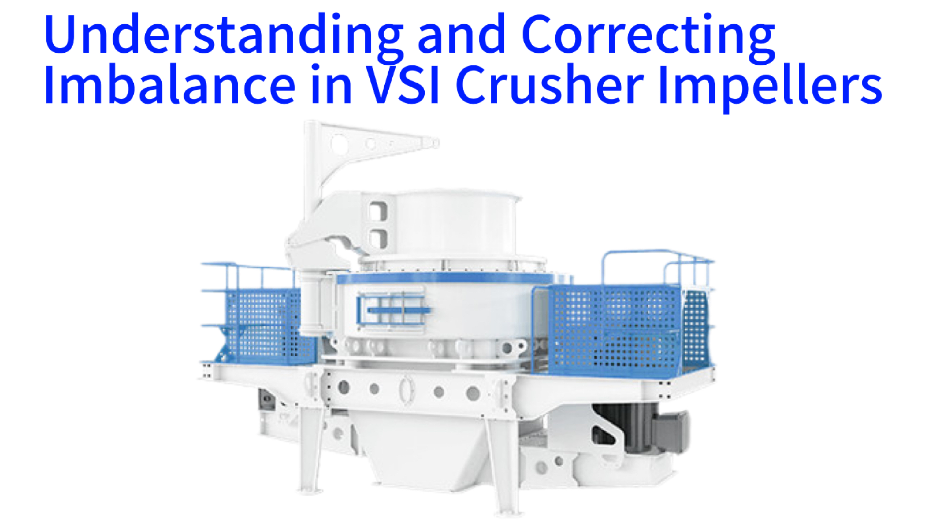
The operation of a Vertical Shaft Impact crusher relies fundamentally on the high-speed rotation of its central component, the impeller or rotor. This precise rotational motion is critical for accelerating material and achieving the desired fragmentation through impact. However, a common mechanical issue known as rotor imbalance can severely disrupt this process, leading to excessive vibration, accelerated wear, and potential equipment failure. This article provides a comprehensive examination of the phenomenon of impeller imbalance in VSI crushers. It systematically explores the underlying physical causes, details the diagnostic procedures for identifying the specific source of imbalance, and outlines a practical methodology for performing initial on-site dynamic balancing corrections. Furthermore, the discussion extends to advanced balancing techniques and foundational preventive maintenance strategies designed to promote long-term operational stability and equipment reliability for this essential crushing machinery.
The Fundamentals of Rotor Imbalance in Impact Crushers
Rotor Imbalance Type & Impact Comparison
| Imbalance Type | Characteristic | Key Symptom | Main Impact |
|---|---|---|---|
| Static | Heaviest point on single side of rotation axis | Single-frequency vibration, bouncing motion | Bearing fatigue, uneven material acceleration |
| Dynamic | Two imbalance forces in different planes (couple) | Rocking/twisting motion, dual-plane vibration | Shaft metal fatigue, frame fastener loosening |
Rotor imbalance represents a condition where the mass distribution around the impeller's axis of rotation is uneven. In an ideal state, the geometric center of the rotor aligns perfectly with its center of mass, allowing for smooth rotation without generating significant centrifugal forces. Practical manufacturing tolerances, material inconsistencies, and operational wear inevitably lead to a slight misalignment. This discrepancy causes the center of mass to be offset from the axis of rotation. During operation, this offset mass generates a centrifugal force that varies in direction but not in magnitude as the rotor spins. It is this repetitive, rotating force that manifests as the perceptible vibration of the entire crusher structure, a primary indicator of an imbalance condition that requires attention.
Defining Static and Dynamic Imbalance
Imbalance in rotating assemblies is categorized into distinct types, primarily static and dynamic. Static imbalance occurs when the heaviest point of the rotor lies directly on one side of the rotational axis. This can be visualized as a weight added to a perfectly balanced wheel; the wheel will not roll smoothly but will bounce. In a VSI crusher context, static imbalance might result from a single, significantly worn impeller shoe or a localized buildup of compacted material. Dynamic imbalance is a more complex condition involving two imbalance forces acting in different planes along the rotor's length, creating a twisting or rocking couple. This type is common in longer rotors and often arises from uneven wear patterns across multiple wear parts or slight misalignments in the rotor assembly itself.
Primary Symptoms and Observable Effects
The most direct consequence of an imbalanced VSI crusher impeller is a measurable increase in overall machine vibration. This vibration is typically synchronous with the rotational speed of the rotor. Operators often report a change in the operational sound of the crusher, transitioning from a consistent hum to a pronounced, rhythmic pounding or shaking. Visually, the crusher's chassis or associated components may exhibit noticeable oscillation. Furthermore, excessive vibration transmits significant stress to the bearing assemblies, frequently leading to an abnormal and sustained rise in bearing housing temperature, which serves as a critical warning sign of impending mechanical distress.
Consequences for Mechanical Integrity
The cyclical stresses induced by imbalance have a profoundly detrimental effect on the crusher's mechanical systems. Rolling element bearings are particularly vulnerable, as the abnormal loads accelerate fatigue, leading to premature spalling and failure. The constant flexing can induce metal fatigue in the main shaft, potentially resulting in catastrophic fracture. Additionally, the vibrating motion can cause fasteners throughout the crusher frame and accessory mounts to gradually loosen, creating secondary points of failure and further exacerbating the vibration issue in a destructive feedback loop.
Impacts on Production Output and Quality
Beyond immediate mechanical damage, an imbalanced rotor detrimentally affects the crushing process itself. The inconsistent motion of the impeller leads to uneven acceleration of feed material. This results in a less predictable particle trajectory within the crushing chamber, often producing a wider and less controlled product gradation. The energy required to drive the vibrating rotor increases, raising overall power consumption. Ultimately, the need for frequent unscheduled shutdowns to address vibration-related issues or component failures directly reduces the crusher's availability and annual throughput capacity.
Analysis of Common Causes for Impeller Mass Distribution Discrepancy
Identifying the root cause of imbalance is a prerequisite for effective correction. The origins can be broadly classified into those arising from operational wear, those introduced during maintenance or repair, and inherent manufacturing factors. A systematic investigation typically begins with the most frequent operational causes before proceeding to examine less common but equally critical structural or assembly-related issues. This diagnostic approach allows maintenance personnel to efficiently pinpoint the problem and select the appropriate remedial action, whether it involves simple cleaning, component replacement, or professional rebalancing.
Asymmetric Wear of Tungsten Carbide Wear Parts
The most prevalent cause of imbalance in active VSI crushers is the non-uniform wear of the replaceable wear components on the impeller. These components, such as impeller shoes, distributor plates, and wear rings, are designed to endure abrasive impact. However, variations in feed material composition, uneven material flow across the feed size distribution, or slight differences in the metallurgical properties of individual wear parts can lead to disparate wear rates. Over time, one section of the impeller may become significantly lighter due to accelerated wear, while another section retains more of its original mass, creating a substantial mass imbalance that directly affects rotational smoothness.
Adhesion and Build-up of Sticky Feed Material
Certain materials processed in VSI crushers, such as clay-bearing aggregates or ores with high moisture content, have a tendency to adhere to metal surfaces. During operation, these materials can accumulate persistently inside the impeller's feed tubes, on the backside of shoes, or on the interior walls of the rotor assembly. This adhered material acts as an unintended and uncontrolled added mass. Since this build-up is rarely symmetrical, it introduces a localized heavy spot on the rotor. Notably, imbalance caused by material build-up can often be rectified through thorough cleaning without the need for adding or removing permanent balance weights, making initial inspection and cleaning a vital first step.
Manufacturing Tolerances and Improper Repair Techniques
Every manufactured rotor has a inherent residual imbalance due to casting irregularities, machining variances, and minor imperfections in material density. Reputable manufacturers perform initial balancing before shipping, but this initial state can be altered. Field repairs, such as rebuilding a worn impeller surface with weld overlay, are a common practice. If this welding is applied unevenly or without subsequent balance checks, it can introduce a significant new imbalance. The added weld metal, while restoring dimension, creates a concentrated mass that disrupts the rotor's original mass distribution, requiring a rebalancing procedure to restore proper operation.
Installation Errors and Component Loosening
Correct installation of wear parts is crucial for maintaining balance. If impeller shoes or distributor plates are not torqued to specification uniformly, they may not seat perfectly flat against the rotor body. This can create a minute axial runout or a subtle shift in the collective center of mass. More critically, under the tremendous centrifugal forces and impact shocks of normal operation, even properly installed components can gradually loosen. A single shoe that becomes slightly displaced alters the rotor's dynamic characteristics immediately, often leading to a sudden onset of severe vibration that necessitates immediate shutdown and inspection.
Preparatory Procedures and Safety Protocols for On-Site Balancing
On-Site Balancing - Safety Protocols & Essential Tools
| Safety Mandatory Protocols | Essential Measurement & Operation Tools |
|---|---|
| ✓ Complete drive motor shutdown | ✓ Portable vibration meter (velocity/displacement) |
| ✓ Lockout & tag all energy sources (electrical/hydraulic) | ✓ Photoelectric tachometer/strobe light (phase/speed) |
| ✓ Confirm zero-energy state before operation | ✓ Calibrated trial weights (clay/magnetic/bolts) |
| ✓ Visual warning tag at isolation point | ✓ Precision hand tools & cleaning supplies |
| ✓ Authorized personnel only for on-site work | ✓ Caliper/depth gauge (wear part measurement) |
Executing any maintenance task on industrial crushing equipment demands strict adherence to safety protocols. Before any attempt at on-site balancing, a formal and rigorous isolation procedure must be completed. This involves the complete shutdown of the crusher's drive motor, followed by the physical disconnection and locking out of all energy sources, including electrical and hydraulic power supplies. A visual tag should be placed on the isolation point to inform all personnel that work is in progress. Only after these life-saving steps are confirmed can personnel safely approach the crusher for inspection and mechanical work, ensuring a zero-energy state for the system.
Initial Visual Inspection and Decontamination Process
The first technical step after safe isolation is a comprehensive visual and manual inspection of the rotor assembly. Maintenance personnel should carefully examine the entire impeller, paying close attention to the condition of all wear parts and the interior cavities. The primary objective is to identify and remove any and all adherent material buildup. This process requires manual scraping, brushing, and potentially the use of specialized cleaning tools to ensure the rotor is in its bare, uncontaminated state. This cleaning phase alone can resolve many imbalance issues, as it eliminates the variable of uneven material accumulation, which is a frequent and easily addressed cause of vibration.
Essential Tooling and Measurement Equipment Checklist
Performing even a basic on-site balance requires a specific set of tools. A reliable vibration meter is fundamental; modern portable devices can measure vibration amplitude in velocity or displacement units and are indispensable for quantifying the problem and tracking improvement. For more advanced work, a photoelectric tachometer or a strobe light is used to determine rotational speed and reference phase angle. The balancing process itself requires temporary trial weights, which can be specialized balancing clay, magnetic weights, or carefully measured bolts and washers. Basic hand tools for installing these weights, a notebook for recording data, and cleaning supplies round out the necessary kit for field correction work.
Establishing Measurement Baselines and Reference Points
Prior to attempting any correction, it is necessary to establish a baseline measurement of the imbalance. After the rotor is clean and confirmed to be mechanically sound, the crusher is started and run at its normal operating speed. The vibration meter probe is placed on a solid, unmoving point on the crusher's bearing housing or main frame. The initial vibration amplitude, typically measured in millimeters per second, is recorded. If the equipment allows, the phase angle of the vibration peak relative to a fixed mark on the rotor shaft should also be noted. This initial data set defines the "as-is" condition and provides a benchmark against which all subsequent balancing adjustments will be measured for effectiveness.
Methodical Four-Step Procedure for Single-Plane Field Balancing
The single-plane field balancing method is a practical technique for correcting a predominant static imbalance without disassembling the rotor. This approach is based on systematically adding and removing known trial weights at the rotor's periphery and measuring the corresponding change in vibration response. By analyzing the relationship between the weight's position and the resulting vibration vector, the required corrective weight and its angular location can be calculated. This method, while not as precise as machine shop balancing, is highly effective for restoring operational stability and mitigating excessive vibration in many field situations, thereby extending the service interval before a more comprehensive overhaul is required.
Initial Data Acquisition of Unbalanced Vibration Signature
The procedure commences with the crusher running under normal operating conditions with a clean rotor. Using the previously established measurement point, the technician records the peak vibration amplitude. For a more accurate calculation, noting the phase angle is highly beneficial. A reflective tape is placed on a visible part of the rotating shaft, and a photoelectric tachometer is aimed at it. The tachometer reads the timing of the tape's pass, correlating the peak vibration reading to a specific angular position on the rotor. This initial run establishes a baseline vector that represents the combined effect of all imbalance forces present in the system at that time.
Application and Testing with a Calibrated Trial Mass
A trial weight of known mass is securely attached to the rotor at a chosen angular location. This weight should be substantial enough to cause a measurable change in vibration but not so large as to risk damage. A common starting point is the outer rim of the impeller. The crusher is then restarted and brought back to the identical operating speed. The vibration amplitude and phase are measured again at the same point. The difference between this new vibration vector and the initial baseline vector is directly attributable to the influence of the trial weight. This step provides the critical data needed to understand how the rotor's mass distribution responds to a known modification.
Vector-Based Calculation for Corrective Weight Parameters
The data from the two runs is analyzed using vector mathematics. The initial vibration vector and the vibration vector with the trial weight are plotted graphically or processed using balancing software. The goal is to find a corrective weight that, when added, will create a force equal and opposite to the original imbalance force. The calculation determines both the optimal angular position for this corrective weight and its required mass relative to the trial weight used. The angle is often significantly different from the point where the trial weight was placed, highlighting the importance of this analytical step over guesswork. For simpler field applications, rule-of-thumb calculations based on amplitude changes can provide an approximate correction.
Final Implementation and Operational Verification
The calculated corrective weight is permanently installed at the specified location on the rotor. This may involve drilling and tapping for a set screw, welding a balance weight, or using an approved adhesive for temporary corrections. After installation, the crusher is started for a final verification run. The vibration levels are measured once more. A successful balance is confirmed by a significant reduction in the overall vibration amplitude, often by 70% or more from the initial reading. If the vibration remains unacceptably high, the procedure may need to be repeated iteratively, or it may indicate the presence of a more complex dynamic imbalance condition requiring a two-plane or professional balancing approach.
Advanced Balancing Methodologies and Instrumentation Overview
Balancing Methodology & Instrumentation Capability
| Method/Instrument | Applicable Scenario | Core Capability | Accuracy & Efficiency |
|---|---|---|---|
| Single-Plane Balancing | Short/disk-like rotors, static imbalance | Single correction plane, basic vector calculation | Moderate accuracy, fast field operation |
| Two-Plane Dynamic Balancing | Long rotors, dynamic couple imbalance | Double correction planes, counteract rocking motion | High accuracy, comprehensive imbalance correction |
| Portable Dynamic Balancer | On-site single/two-plane balancing | Integrated vibration/phase sensor, auto vector calculation | High accuracy, time-saving (50%+ efficiency) |
| Laser Shaft Alignment Tool | Shaft-drive motor misalignment check | Precise alignment, eliminate vibration from misalignment | Ultra-high accuracy, prevent false balancing |
While single-plane balancing addresses many common issues, certain rotor configurations and precision applications demand more sophisticated techniques. Professional balancing employs advanced principles and dedicated instrumentation to achieve a higher standard of rotational smoothness. These methods are particularly relevant for very high-speed crushers, custom rotor designs, or situations where the initial field correction proved insufficient. Understanding these advanced options allows operators to make informed decisions about when in-house correction is adequate and when the services of a specialized balancing technician or the use of a dedicated balancing machine are justified for optimal long-term performance.
Two-Plane Dynamic Balancing for Extended Rotor Assemblies
The single-plane method assumes the imbalance force acts through a single point, which is valid for relatively short, disk-like rotors. For longer rotors, such as those found in some larger VSI crusher models, an imbalance condition often manifests as a force couple—two equal and opposite imbalance forces acting at different points along the shaft. This creates a rocking motion that cannot be corrected by a weight in one plane alone. Two-plane balancing requires taking vibration and phase measurements at both ends of the rotor assembly. Corrective weights are then calculated and applied in two separate correction planes, typically near the ends of the rotor, to counteract both the static imbalance and the rocking couple, resulting in superior smoothness across the entire bearing span.
Capabilities of Modern Portable Dynamic Balancing Instruments
Contemporary portable balancers have transformed field maintenance. These instruments integrate a vibration sensor, a phase reference tachometer, and a dedicated microprocessor. The technician follows an interactive on-screen procedure: measuring initial vibration, attaching a trial weight, and taking a second measurement. The instrument's software automatically performs the vector calculations and instantly displays the required corrective weight mass and its precise angular position, often down to the degree. Some advanced models can store the "influence coefficients" for a specific machine, making repeat balancing in the future even faster and more accurate. This technology greatly reduces the skill barrier and time required for effective field balancing.
The Integral Role of Precise Shaft and Drive Alignment
It is imperative to recognize that vibration symptoms mimicking imbalance can originate from other sources. Misalignment between the crusher's main shaft and the drive motor shaft is a primary example. A misaligned coupling induces forces at rotational speed and often at twice rotational speed, which can be mistaken for imbalance. Therefore, a comprehensive vibration analysis should always precede major balancing work. Using a laser alignment tool to ensure precise shaft alignment is a critical preventive measure. Proper alignment minimizes baseline vibration, ensures that any subsequent balancing effort is correcting a genuine mass distribution issue rather than a coupling problem, and protects both the crusher and motor bearings from premature failure.
Proactive Maintenance Strategies to Mitigate Imbalance Occurrence
Proactive Maintenance for Imbalance Mitigation
| Maintenance Strategy | Core Implementation Measures | Expected Outcome |
|---|---|---|
| Scheduled Rotor Inspection & Cleaning | - Fixed interval (per production cycle) disassembly - Thorough build-up removal - Quantitative wear measurement at fixed points | - Eliminate build-up-induced imbalance - Early detect asymmetric wear - 30%+ reduction in sudden vibration issues |
| Wear Part Mass Management & Replacement | - Replace wear parts as a complete set - Weigh and match part mass (minimize variance) - Rotate parts to uniformize wear | - Preserve rotor mass symmetry - Reduce residual imbalance after replacement - Extend balancing interval by 50%+ |
| Continuous Vibration Trend Monitoring | - Install permanent bearing vibration sensors - Real-time data logging & remote monitoring - Set vibration alarm thresholds | - Early imbalance detection (gradual vibration rise) - Predictive maintenance scheduling - Eliminate unplanned production shutdowns |
| Regular Shaft Alignment & Fastener Check | - Laser alignment for main/drive shaft - Torque verification of all rotor fasteners - Periodic coupling inspection | - Eliminate misalignment-induced vibration - Prevent component loosening - Extend bearing/motor service life |
A strategic shift from reactive repair to proactive prevention is the most effective long-term approach to managing rotor imbalance. By integrating specific inspection and maintenance practices into the standard operating protocol, the frequency and severity of imbalance events can be dramatically reduced. These strategies focus on controlling the variables that lead to uneven mass distribution, primarily wear and contamination. MSW Technology, drawing upon fifteen years of field experience with industrial crushing systems, emphasizes that a disciplined maintenance routine is less costly and far more productive than responding to unplanned breakdowns caused by neglected vibration issues.
Scheduled Rotor Inspection and Systematic Cleaning Regimes
Establishing a fixed interval for rotor inspection is paramount. During planned maintenance shutdowns, technicians should thoroughly examine the impeller. This involves checking for and removing any material build-up, as previously detailed. More importantly, it requires a quantitative assessment of wear part condition. Using calipers or depth gauges, the remaining thickness of impeller shoes and liners should be measured at multiple, consistent points. Documenting these measurements over time reveals wear patterns. Identifying trends of asymmetric wear allows for proactive intervention, such as rotating or replacing wear parts before they cause a severe imbalance, thereby maintaining consistent crushing capacity and product quality.
Protocols for Wear Part Replacement and Mass Management
When replacing worn components, a key practice is to manage the collective mass of the new parts. For instance, impeller shoes should ideally be replaced as a complete set rather than individually. Before installation, each new shoe can be weighed on a scale. By selecting a set of shoes with nearly identical masses, the initial mass symmetry of the rotor is preserved. Any new part that is a significant outlier in weight should be set aside or potentially modified. This simple practice of mass matching during assembly minimizes the inherent residual imbalance introduced during component change-outs, providing a much more stable starting point for the next operational campaign and reducing the need for immediate balancing.
Implementing Vibration Trend Monitoring for Early Detection
Modern condition monitoring technology offers a powerful tool for imbalance prevention. Permanent vibration sensors can be installed on the crusher's bearing housings and connected to a data acquisition system. This system continuously logs vibration levels, creating a long-term trend. Operators and maintenance planners can monitor this trend remotely. A gradual, steady increase in vibration amplitude over weeks or months is a clear indicator of progressing imbalance, likely due to uneven wear. This early warning allows the team to schedule a balancing correction at the next convenient maintenance window, preventing the vibration from escalating to a level that risks component failure and causes unplanned production stoppages, thus optimizing overall plant efficiency.