Sustaining Peak Performance: Component Care for the MH Series Cone Crusher
MH Series Cone Crusher Maintenance Workflow
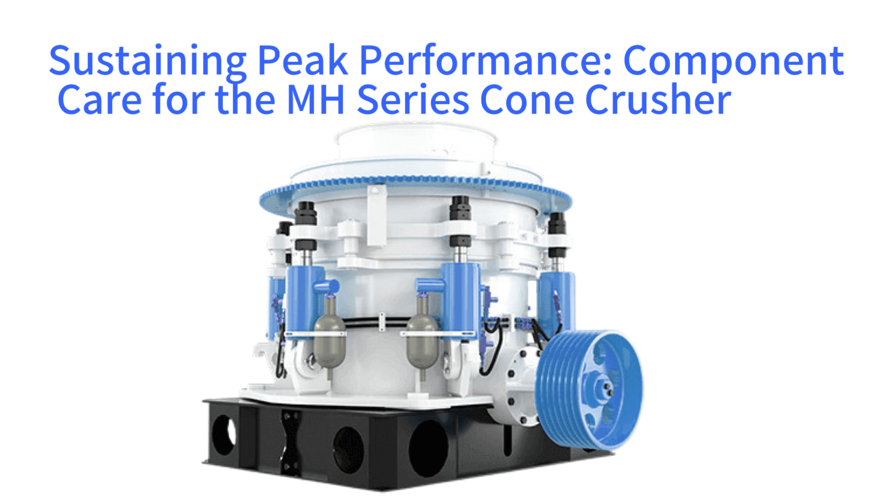
The MH Series Multi-Cylinder Hydraulic Cone Crusher represents a sophisticated piece of industrial machinery designed for high-volume secondary and tertiary crushing. Its reliable operation depends on the systematic maintenance and timely replacement of its key components. This article provides a detailed examination of the practical steps and critical considerations for preserving this machine's functionality. A focus is placed on the wear parts that interact directly with abrasive feed material, the complex hydraulic systems that govern its adjustment and protection, and the major mechanical assemblies that form its structural core. Understanding these procedures extends the operational lifespan of the equipment, ensures consistent product quality, and prevents catastrophic failures that lead to extensive downtime. The following sections will explore the foundational concepts of the crusher's operation to contextualize maintenance needs, outline a disciplined routine inspection protocol, detail the specific tasks for the lubrication and hydraulic systems, guide the replacement process for manganese wear liners, address the maintenance of the main shaft and eccentric assembly, and finally discuss strategies for diagnosing common operational issues and managing replacement part inventories effectively.
Understanding the Crusher's Operational Principles
| Hydraulic System Function | Key Component | Failure Impact |
|---|---|---|
| Closed-Side Setting (CSS) Adjustment | Hydraulic Cylinders | Inconsistent Product Size |
| Overload Protection | Accumulator | Catastrophic Component Damage |
| Cavity Clearing | Control Valves | Extended Downtime |
The MH Series crusher operates on a gyratory compression principle. The core of its function involves a rotating mantle attached to a moving cone, which gyrates within a stationary concave liner. This gyratory motion is created by an eccentric bushing driven by a pinion and gear arrangement from the crusher's main shaft. The multi-cylinder hydraulic system integrated into this design serves multiple simultaneous purposes. It provides the necessary force to adjust the crusher's closed-side setting, which directly controls the size of the output product. It also functions as a safety mechanism by allowing the mantle to drop and release any uncrushable material that enters the crushing chamber, a feature known as hydraulic overload protection. This release prevents damage to the mechanical components from tramp iron or other uncrushable objects.
This continuous interplay between mechanical force and hydraulic control subjects specific components to predictable stress and wear patterns. The concave and mantle liners endure direct abrasive wear from tons of rock processed every hour. The hydraulic cylinders and their seals operate under high pressure and are susceptible to fluid contamination and seal degradation. The bronze eccentric bushing and the main shaft bearings facilitate the precise gyratory motion and must be protected from inadequate lubrication. A thorough grasp of these operational interactions is not merely academic. It forms the essential foundation for all maintenance decisions, enabling personnel to predict wear, interpret symptoms of decline, and execute component replacements before failures compromise production or damage more expensive sub-assemblies. This knowledge transforms maintenance from a reactive chore into a predictive science focused on asset preservation.
The Role of the Multi-Cylinder Hydraulic System
The hydraulic system is the defining feature of the MH Series crusher, distinguishing it from older spring-type cone crushers. Several hydraulic cylinders are arranged around the crusher's body, connected to the moving cone assembly. During normal crushing, these cylinders apply a consistent pressure to maintain the crusher's setting and absorb the crushing forces. When an uncrushable object enters the chamber, the pressure in the hydraulic system spikes rapidly. The system is designed to relieve this pressure by allowing the hydraulic oil to bypass into an accumulator, which permits the entire moving cone assembly to lower momentarily. This action opens the discharge gap, allowing the foreign object to pass through without transferring destructive shock loads through the gear and shaft components.
This system's health is paramount. It relies on clean hydraulic oil, intact cylinder rods free from scoring, and resilient piston seals. Contaminated oil containing microscopic metal particles or moisture can abrade critical surfaces inside hydraulic pumps and control valves. Worn cylinder seals lead to internal leakage, causing the crusher's setting to drift during operation and resulting in an inconsistent product size distribution. The hydraulic system also incorporates complex valving for setting adjustment and cavity clearing functions. Therefore, maintenance of this system extends beyond simple fluid changes to include regular checks of pressure readings, monitoring for unusual cycle times during adjustment, and inspecting all hydraulic hoses and fittings for signs of wear or leakage that could indicate impending failure.
Identifying Key Wear Components and Their Functions
Within the crushing chamber, the components experiencing the most direct and severe wear are the manganese steel liners: the concave (or bowl liner) and the mantle. The concave is a stationary lining fixed to the adjusting ring, forming the outer surface of the crushing chamber. The mantle is a conical wear part mounted on the main shaft, forming the inner, gyrating surface. Rock is fed into the gap between these two surfaces and is crushed by the compressive gyratory action. The profile of these liners—their curvature and angle—determines the crusher's cavity type, which influences capacity, product shape, and liner wear life. Common profiles include coarse, medium, fine, and extra-fine.
Other critical wear items include the feed plate or distribution plate at the top of the crusher, which directs incoming material evenly into the crushing chamber to promote uniform liner wear. The eccentric bushing, a large bronze component, allows the main shaft to gyrate smoothly. Although not in direct contact with the feed material, it wears from the constant rotational friction against the shaft. The main shaft itself can suffer wear at the points of contact with the eccentric bushing and the thrust bearing. Pinion and bevel gears transmit power from the drive motor to the eccentric assembly, and their teeth are subject to fatigue and wear over time. Recognizing the distinct function and failure mode of each part allows for targeted maintenance planning and accurate troubleshooting when performance issues arise.
Establishing a Foundational Routine Inspection Protocol
| Monitoring Indicator | Normal Range | Alarm Threshold |
|---|---|---|
| Lube Oil Return Temperature | 45°C - 55°C (113°F - 131°F) | >60°C (140°F) |
| Hydraulic System Pressure | Variable (per CSS/feed) | >Max Design Pressure |
| Vibration Amplitude | Baseline ±10% | >Baseline ±25% |
Effective maintenance for an MH Series crusher begins with a disciplined and consistent routine inspection schedule. These inspections are designed to identify early signs of wear, misalignment, or system degradation before they evolve into major problems. Daily checks, often performed at the start of each operating shift, form the first line of defense. An operator should visually inspect the crusher's exterior for any signs of oil leaks, particularly around the hydraulic cylinder seals, lubrication pipe connections, and the dust seal rings. Auditory checks are also valuable; unusual noises such as persistent knocking, grinding, or squealing can indicate issues with liner wear, inadequate lubrication, or bearing problems.
These daily inspections should include a review of the crusher's operational data. The lubrication system should be verified for proper oil flow and pressure, as indicated on the console gauges. The temperature of the return oil from the bearings is a critical health indicator; a steady rise in temperature can signal bearing distress, contamination in the oil, or a clogged cooler. The hydraulic system pressure should be noted to ensure it remains within the normal operating range for the current crusher setting. Any significant deviation from baseline pressure readings can suggest issues like worn liners, incorrect settings, or hydraulic system inefficiency. Documenting these observations in a maintenance log creates a historical record that is invaluable for trend analysis and predictive maintenance.
Weekly and Monthly Detailed Visual and Operational Checks
Beyond daily observations, more detailed weekly and monthly inspections provide a deeper assessment of component condition. A weekly check might involve a more thorough examination of the crusher's dust seal. This seal prevents abrasive rock dust from contaminating the lubricated eccentric bushing and lower bearings. Inspectors should look for excessive dust buildup around the seal area or signs of oil seepage from the seal, which would indicate seal failure. The tension of the drive belts should be checked to ensure proper power transmission without slippage, which can cause accelerated wear on both the belts and the sheaves.
Monthly inspections delve into the internal condition indirectly. A primary task is to measure the crusher's wear liners. This is typically done by checking the closed-side setting (CSS) using a lead measurement method or, in more modern setups, via the crusher's own hydraulic positioning system and wear compensation software. A gradual reduction in the mantle's thickness will cause the CSS to increase if not corrected. Tracking the rate of CSS change over time provides a direct measure of liner wear rate and allows for accurate prediction of the remaining liner life. Monthly checks should also include verifying the condition and level of all fluid systems—hydraulic oil, lubrication oil, and the coolant in the heat exchangers. Fluid samples should be taken periodically for laboratory analysis to detect the presence of wear metals, water, or other contaminants that are not visible to the naked eye.
Utilizing Condition Monitoring and Data Analysis Tools
Modern cone crushers are often equipped with advanced condition monitoring sensors that augment visual inspections. Vibration sensors mounted on the main frame and the lube oil tank can detect abnormal frequencies associated with unbalanced rotating masses, gear mesh issues, or bearing defects. Online particle counters in the lubrication system can provide real-time data on the concentration and size of wear metals in the oil, offering an early warning of internal component degradation. Thermocouples monitor bearing temperatures at multiple points, providing a more precise picture than a single return line temperature gauge.
The true power of this data lies in its analysis over time. Establishing baseline vibration spectra and temperature profiles when the crusher is new or freshly overhauled creates a reference point. Subsequent data is compared against these baselines. A trending increase in vibration amplitude at a specific frequency can pinpoint a developing fault long before it becomes audible. Similarly, a gradual rise in bearing operating temperature, even within the "normal" range on a gauge, can indicate declining lubrication efficiency or the early stages of bearing fatigue. Integrating these electronic condition monitoring tools with traditional inspection logs creates a comprehensive predictive maintenance program. This program shifts the maintenance paradigm from running components to failure to replacing them at the optimal point, maximizing component life while minimizing the risk of unplanned stoppages.
Maintaining the Lubrication and Hydraulic Fluid Systems
| Contamination Control Task | Standard | Frequency |
|---|---|---|
| Hydraulic Fluid Filtration | ISO 4406: 18/15/12 | Continuous (Filter Cart) |
| Oil Analysis | Wear Metals < 50 ppm | Monthly/Quarterly |
| Reservoir Breather Replacement | 5 Micron Filtration | 6 Months |
The lifeblood of the MH Series crusher is its fluid systems. Separate but equally critical, the lubrication system and the hydraulic system demand meticulous care. The lubrication system is dedicated to delivering a continuous flow of clean, cool oil to the crusher's internal bearings, gears, and sliding surfaces. This includes the main shaft bearings, the eccentric bushing, the bevel gear and pinion, and the piston rings for the hydraulic cylinders in some designs. The oil performs three essential functions: it reduces friction between metal surfaces, it carries away heat generated by that friction, and it flushes away microscopic wear particles. A failure in any of these functions leads directly to accelerated component wear and potential seizure.
Maintaining this system requires adherence to strict schedules. The lubricating oil must be changed at intervals specified by the manufacturer, typically after a certain number of operating hours or based on oil analysis results. The oil filters must be replaced or cleaned regularly to prevent clogging, which would restrict flow and cause a pressure differential alarm. Oil coolers, whether air-blast or water-cooled, must be kept clean to ensure efficient heat transfer; a clogged cooler will cause oil temperatures to rise, reducing its viscosity and lubricating effectiveness. Regular checks of the oil level in the tank are essential, as a dropping level can indicate an external leak or, more seriously, internal leakage into the crushing chamber or hydraulic system. The use of a high-quality oil with the correct viscosity grade and additive package, as specified in the crusher's manual, is a non-negotiable requirement for long-term reliability.
Hydraulic System Care and Contamination Control
The hydraulic system's reliability hinges on fluid cleanliness. Contaminants such as dirt, metal shavings, and water are the primary enemies of hydraulic pumps, servo valves, and cylinder seals. These contaminants cause abrasive wear, clog orifices, and promote corrosion. Therefore, the first rule of hydraulic maintenance is rigorous contamination control. All hydraulic fluid added to the system must be filtered through a portable filter cart. Reservoir breathers must be of the proper filtration grade to prevent airborne dust from entering during tank breathing cycles. Hoses should be replaced on a preventive schedule before they age and begin shedding inner tube material into the fluid.
Routine maintenance tasks include checking and cleaning the suction strainer in the hydraulic tank, replacing high-pressure filter elements, and monitoring the condition of the hydraulic fluid itself. Fluid analysis is as important for the hydraulic system as for the lube system. The analysis tests for viscosity, water content, particulate contamination level, and the presence of additive depletion. The system's accumulator, a key component for the overload release function, requires periodic checks of its pre-charge nitrogen pressure. A loss of pre-charge pressure will cause the crusher to react sluggishly to overloads and may not provide sufficient force to quickly reset the crusher after a tramp iron event. All hydraulic hose connections and cylinder rod surfaces should be inspected for leaks; a leaking cylinder seal will not only waste fluid but can allow contaminants to be drawn into the system as the cylinder retracts.
Managing System Pressures and Temperature Parameters
Operating the crusher within its designed pressure and temperature ranges is critical for component longevity. The lubrication system operates with specific pressure requirements. The oil pump must generate enough pressure to ensure flow reaches all lubrication points, especially the main shaft bearings at the top of the crusher. A pressure sensor typically monitors this, and a low-pressure switch will stop the crusher if flow is inadequate to prevent bearing damage. The temperature of the lubrication oil leaving the bearings is a direct indicator of bearing health and cooling efficiency. A normal operating range might be between 45°C and 55°C (113°F to 131°F). Sustained operation above 60°C (140°F) warrants investigation into cooler performance, oil viscosity, or bearing condition.
The hydraulic system pressure is variable and directly correlates with the crushing force. The operating pressure is set according to the desired product size and the hardness of the feed material. It is crucial not to exceed the maximum allowable system pressure, as this can overstress hoses, fittings, and cylinders. The pressure relief valve setting must be checked periodically to ensure it functions correctly. Temperature also affects the hydraulic system. Hot hydraulic oil becomes thinner, which can lead to increased internal leakage in pumps and valves, reducing system efficiency and control accuracy. Monitoring these pressures and temperatures daily, understanding their normal values, and investigating any deviations form a core practice of proactive maintenance that prevents slow, cumulative damage to these expensive and complex fluid power systems.
The Concave and Mantle Liner Replacement Procedure
| Liner Type | Cavity Profile | Typical Replacement Interval |
|---|---|---|
| Concave/Mantle | Coarse | 4-8 Weeks (High Abrasion) |
| Concave/Mantle | Fine | 8-12 Weeks (High Abrasion) |
| Feed Plate | - | 2-3 Liner Changes |
Replacing the manganese wear liners is the most frequent major maintenance activity on a cone crusher. The concave liners and the mantle are sacrificial components designed to wear out, protecting the much more costly underlying structures of the adjusting ring and the main shaft head. The replacement interval depends on the abrasiveness of the feed material, the crusher's throughput, and the selected cavity profile, but it may range from several weeks to a few months in high-abrasion applications. Planning this replacement during a scheduled maintenance shutdown is far more efficient than waiting for a liner to wear completely through, which risks damage to the backing material or the crusher body itself.
The process begins with preparation and safety. The crusher must be completely isolated from power sources, and the hydraulic system pressure must be bled off. All tools, lifting equipment, and the new liner sets must be assembled at the work site. The general sequence involves first removing the feed plate or distribution cone to access the top of the crushing chamber. The old mantle is then removed from the main shaft head. This typically requires unthreading a large retaining nut or removing mounting bolts, a task for which specialized hydraulic torque wrenches are often used due to the extreme torque values involved. With the mantle removed, the old concave segments can be taken out from the top. The number of segments varies by crusher size, but each is heavy, requiring careful rigging and crane operation.
Removing Worn Liners and Preparing Mounting Surfaces
The actual removal of worn liners requires methodical steps. For the mantle, after the retaining device is loosened, it is common practice to use a lifting eye threaded into the top of the mantle itself. The mantle is then lifted straight up and off the tapered head of the main shaft. It is crucial to inspect the mantle's mounting surface and the corresponding surface on the main shaft head for any wear, cracks, or corrosion. These surfaces must be clean and smooth to ensure the new mantle seats perfectly; any high spots should be carefully ground down, and the surfaces should be cleaned with a solvent to remove old sealant and debris.
Removing the concave segments involves a different approach. After the mantle is out, access to the concave is open. Many designs use a locking system where segments are held radially by adjacent segments and from behind by the adjusting ring. A common method is to use a chain fall or crane to lift one segment slightly, breaking its contact, and then pulling it inward toward the center of the chamber before lifting it out. As each segment is removed, the backing material—usually a pourable epoxy-like compound called zinc or a non-shrink grout—is chipped away from the adjusting ring's inner surface. This backing material is essential as it provides a solid, even support for the concave; it must be entirely removed to prepare for the installation of the new liners. The adjusting ring threads and the mating threads on the main frame should also be cleaned and inspected for damage at this time.
Installing New Liners and Ensuring Proper Alignment
The installation of new liners is a precision task. The process is essentially the reverse of removal, but with added critical steps for ensuring longevity. First, the correct liner set must be verified for the desired cavity profile. The new concave segments are lowered into the adjusting ring. Before the final positioning, a measured amount of backing material is mixed and poured behind each segment. The segments are then pressed firmly against the adjusting ring using temporary jacks or bolts, and the backing material is allowed to cure completely as per the manufacturer's specifications. This creates a solid, monolithic support that prevents the manganese steel from flexing under load, which would lead to premature cracking.
Installing the new mantle is equally precise. The sealing surfaces on the main shaft head and the mantle's bore are coated with a suitable sealant to prevent fine rock dust from infiltrating and causing corrosion or making future removal difficult. The mantle is carefully lowered onto the shaft head, ensuring it seats fully on its taper. The large retaining nut or bolt assembly is then tightened to the exact torque specified in the manual. Under-torquing can allow the mantle to work loose; over-torquing can overstress the threads or distort the mantle. Finally, the feed distribution plate is reinstalled. After assembly, it is good practice to rotate the crusher's moving cone assembly manually by barring the drive sheave to ensure no internal binding occurs before reconnecting power and conducting a no-load test run.
Maintenance of the Main Shaft, Eccentric, and Drive Assembly
| Component | Allowable Wear Clearance | Gear Backlash Specification |
|---|---|---|
| Eccentric Bushing | < 0.5mm (0.020") | - |
| Pinion/Bevel Gear | - | 0.15-0.30mm (0.006-0.012") |
| Main Shaft Bearings | < 0.25mm (0.010") | - |
While liner replacements are frequent, the maintenance of the crusher's core mechanical drive assembly is less common but vastly more critical. This assembly includes the main shaft, the eccentric bushing, the thrust bearing, and the pinion and bevel gear set. These components are designed for long service life, often measured in years, but their condition directly dictates the crusher's mechanical efficiency, noise levels, and ultimate lifespan. Preventive maintenance for this assembly focuses overwhelmingly on lubrication and periodic inspection. The continuous flow of clean, cool oil to the eccentric bushing and the main shaft bearings is the single most important factor in their longevity.
Routine inspections involve listening for changes in the crusher's operating sound. A healthy crusher has a steady, rhythmic hum. The development of a cyclic knocking sound can indicate a worn eccentric bushing, as the clearance between the bushing and the main shaft allows for impact at each revolution. A high-pitched whine or grinding noise may suggest issues with the gear mesh or a bearing starting to fail. Vibration analysis, as part of a condition monitoring program, is particularly effective for these internal components. An increase in vibration at the frequency corresponding to the crusher's rotational speed points to imbalance or shaft issues, while vibrations at gear mesh frequencies indicate pinion or bevel gear wear. Regular oil analysis is also indispensable; a trending increase in copper content points directly to eccentric bushing wear, while elevated iron levels can indicate gear or bearing wear.
Bearing Inspection and Eccentric Bushing Wear Assessment
The main shaft is supported by a combination of radial bearings and a thrust bearing. The thrust bearing carries the entire axial load generated during crushing. These bearings are typically bronze-based and lubricated by the central oiling system. Direct inspection requires significant disassembly, so indirect methods are primary. Monitoring the temperature of the lube oil return from the bearing housing is standard practice. A steady climb in temperature, assuming oil flow and cooler performance are normal, is a strong indicator of bearing distress, such as fatigue, contamination embedding, or loss of clearance.
The eccentric bushing is a large, bronze sleeve that fits between the main shaft and the eccentric assembly. Its inner surface is in constant sliding contact with the main shaft. Wear is inevitable and manifests as increased clearance. This clearance can be checked during major overhauls by measuring the "lift" or "drop" of the main shaft. Excessive clearance leads to loss of precise gyration, causing poor crushing performance, increased vibration, and accelerated wear on the gear teeth. When wear exceeds tolerance, the bushing must be replaced. This is a major task requiring the disassembly of the entire top half of the crusher, including the removal of the moveable cone assembly. The new bushing must be installed with the correct interference fit and alignment to ensure even load distribution and proper lubrication grooves are aligned with the oil supply passages.
Gear Drive Alignment and Backlash Measurement
The pinion and bevel gear set transmits power from the electric motor to the eccentric assembly. Proper alignment and gear backlash are critical for smooth power transmission, minimal noise, and long gear life. Misalignment causes uneven loading across the gear teeth faces, leading to premature pitting and spalling. Backlash, the slight clearance between meshing teeth, is necessary to accommodate thermal expansion and ensure the gears do not bind, but it must be within the manufacturer's specified range. Too little backlash causes overheating and scoring; too much leads to impact loading and noise.
Checking gear alignment and backlash is typically part of an annual or bi-annual major inspection. It involves removing inspection covers and using dial indicators to measure the gear tooth contact pattern and the amount of backlash at several points around the gear. Adjustments are made by shimming the motor and pinion assembly or, in some designs, by adjusting the position of the entire countershaft bearing housing. These adjustments require precision and reference to the crusher's service manual. After any adjustment, the crusher should be run at no-load for a period while gear noise and housing temperatures are monitored to verify the correction was successful. Proper maintenance of this drive train ensures efficient energy transfer and prevents catastrophic gear failures that result in weeks of downtime for repairs.
Diagnosing Common Issues and Managing Replacement Parts
| Spare Part Category | Examples | Inventory Strategy |
|---|---|---|
| Fast-Moving (Wear Parts) | Liners, Seals, Belts | Running Inventory (1-2 Sets) |
| Critical (Long-Life) | Main Shaft, Eccentric, Pumps | Insurance Spares (1 Set) |
| Consumables | Filters, Gaskets, Bolts | Maintenance Kit Stock |
Even with exemplary maintenance, cone crushers will eventually exhibit operational issues. The ability to accurately diagnose these problems saves time and prevents unnecessary part replacements. Common symptoms include unusual noise, decreased throughput, poor product shape, excessive power draw, or hydraulic system alarms. Each symptom can have multiple potential causes, requiring a logical, step-by-step diagnostic approach. For instance, a drop in crusher throughput could be caused by worn liners (increasing the CSS), a clogged feed, a slipping drive belt, or a problem with the feed material itself, such as increased moisture or hardness. Isolating the variable begins with checking the most accessible and common causes first, like the CSS and feed conditions, before moving to more complex internal checks.
Effective diagnosis relies heavily on the operational data and inspection records previously discussed. Trend lines from oil analysis showing rising silicon levels might point to a failing dust seal allowing abrasive fines into the lube oil. A gradual increase in vibration at a specific frequency, correlated with a change in noise, can pinpoint a failing bearing long before it causes secondary damage. Hydraulic system issues often present as an inability to maintain setting or slow cycling times; troubleshooting starts with checking fluid levels, filter conditions, and accumulator pre-charge before suspecting pump or valve failures. Developing this diagnostic skill set in maintenance personnel is as important as teaching them the replacement procedures, as it prevents the wasteful practice of changing parts based on guesswork rather than evidence.
Building a Strategic Inventory of Critical Spare Parts
Managing the inventory of spare parts for an MH Series crusher is a balance between cost and risk. Stocking every possible part is financially impractical, but having no spares guarantees extended downtime when failures occur. The strategy involves categorizing parts based on their criticality, wear rate, and lead time for procurement. Wear parts like mantles, concaves, and dust seal rings are "fast-moving" items with predictable lifecycles. A calculated stock should be maintained based on the crusher's consumption rate and a safety buffer to cover supply chain delays. These are often classified as "running inventory."
Critical, long-life components form a different category. Items like the main shaft assembly, the eccentric, the pinion shaft, or major hydraulic pumps have very long service lives but are extremely expensive and have long manufacturing lead times, sometimes exceeding six months. The consequences of their failure without a spare are severe, involving weeks of lost production. For these, a risk-based decision is required. Many operations choose to stock a single set of these "insurance" spares, sometimes even on a shared basis across multiple sites within a company. Other parts, like specific seals, gaskets, bolts, and sensors, are relatively inexpensive and should be kept in a general maintenance kit. A well-organized and documented parts inventory, linked to the crusher's maintenance history and wear rate forecasts, transforms the parts room from a storage area into a strategic tool for maximizing crusher availability.
Documenting Procedures and Building Maintenance Competency
The final, overarching aspect of effective component maintenance is knowledge management. Every inspection, adjustment, replacement, and repair must be documented in detail. This documentation should include the date, personnel involved, parts used with serial numbers, measurements taken (like CSS, backlash, pressures), and observations. This logbook becomes an invaluable asset. It allows new personnel to understand the machine's history, helps identify recurring issues, and provides data for refining maintenance intervals and procedures. In the context of a major component replacement, such as the concave or the entire eccentric assembly, detailed work instructions and checklists specific to the site's equipment should be developed and followed to ensure consistency and safety.
Building competency within the maintenance team is equally vital. Training should not be a one-time event but an ongoing process. It should cover the theoretical operation of the crusher, the specific procedures for the MH Series model on site, safe work practices for heavy lifting and working at height, and the interpretation of condition monitoring data. Cross-training ensures more than one person understands key tasks. Encouraging technicians to review the historical logs before undertaking work helps them anticipate challenges. This combination of thorough documentation and a skilled, knowledgeable team ensures that the complex task of maintaining a multi-cylinder hydraulic cone crusher is performed efficiently, safely, and to a high standard, safeguarding the substantial capital investment the machine represents and securing its contribution to production goals for years to come.